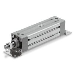
Specifications
Type
Action
Fluid
Proof pressure
Maximum operating pressure
Minimum operating pressure
Non-lube
Double acting, Single rod
Air
1.5 MPa
1.0 MPa
0.05 MPa
Without auto switch –10 to 70°C (No freezing)
With auto switch –10 to 60°C (No freezing)
Not required (Non-lube)
50 to 1000 mm/s
Up to 250: , 251 to 1000: , 1001 to 1500:
Both ends (Air cushion)
JIS Class 2
Basic style, Foot style, Rod side flange style, Head side flange style
Single clevis style, Double clevis style
32 40 63 100
+1.0
0
Standard Stroke
32
40
50
63
80
100
Bore size
(mm)
25, 50, 75, 100, 125, 150, 175, 200, 250, 300, 350, 400, 450, 500
25, 50, 75, 100, 125, 150, 175, 200, 250, 300, 350, 400, 450, 500
25, 50, 75, 100, 125, 150, 175, 200, 250, 300, 350, 400, 450, 500, 600
25, 50, 75, 100, 125, 150, 175, 200, 250, 300, 350, 400, 450, 500, 600
25, 50, 75, 100, 125, 150, 175, 200, 250, 300, 350, 400, 450, 500, 600, 700, 800
25, 50, 75, 100, 125, 150, 175, 200, 250, 300, 350, 400, 450, 500, 600, 700, 800
Standard stroke (mm)
50 80
+1.4
0
+1.8
0
Note)
Rc 1/8 Rc 1/4 Rc 1/4 Rc 3/8 Rc 3/8 Rc 1/2
Note) In the case of w/o air cushion, it comes with rubber bumper.
Maximum
manufacturable
stroke
700
800
1200
1200
1400
1500
Note) Intermediate strokes are available, too. (Spacer is not used.)
Accessory
Mounting
Standard
equipment
Option
Rod end nut
Clevis pin
Single knuckle joint
Double knuckle joint
(With pin)
Rod boot
Basic
style
Foot
style
Rod side
flange style
Head side
flange style
Single
clevis style
Double
clevis style
Rod Boot Material
Symbol
J
K
Rod boot material
Nylon tarpaulin
Heat resistant tarpaulin
Maximum ambient temperature
70°C
110°C
∗ Maximum ambient temperature for the rod boot itself.
JIS Symbol
Double acting
∗
Switch Spacer Part No.
Applicable bore size (mm)
32, 40 50, 63
BMP1-032
80, 100
Part no.
Mounting Bracket Part No.
Foot
Flange
Single clevis
Double clevis
(1)
Bore size
(mm)
32
MB-L03
MB-F03
MB-C03
MB-D03
40
MB-L04
MB-F04
MB-C04
MB-D04
50
MB-L05
MB-F05
MB-C05
MB-D05
63
MB-L06
MB-F06
MB-C06
MB-D06
80
MB-L08
MB-F08
MB-C08
MB-D08
100
MB-L10
MB-F10
MB-C10
MB-D10
앬
앬
앬
앬
앬
앬
—
앬
앬
앬
앬
—
앬
앬
앬
앬
—
앬
앬
앬
앬
—
앬
앬
앬
앬
—
앬
앬
앬
Ambient and fluid temperature
Lubrication
Piston speed
Stroke length tolerance
Cushion
Thread tolerance
Port size
Mounting
Note 1) Order two foot brackets per cylinder.
Note 2) Accessories for each mounting bracket are as follows. Foot, Flange,
Single clevis: Body mounting bolt, Double clevis: Clevis pin, Cotter pin 씮 For details, refer to
page 6-7-11.
Bore size (mm)
-XA쏔
-XB5
-XB6
-XB13
-XC3
-XC4
-XC5
-XC6
-XC7
-XC8
-XC9
-XC10
-XC11
-XC12
-XC14
-XC18
-XC22
-XC27
-XC29
-XC30
-XC35
-X846
Change of rod end shape
Oversized rod cylinder
Heat resistant cylinder (150 °C)
Low speed cylinder (5 to 50 mm/s)
Special port location
With heavy duty scraper
Heat resistant cylinder (110 °C)
Piston rod and rod end nut made of stainless steel
Tie-rod, cushion valve, tie rod nut, etc.
made of stainless steel
Adjustable stroke cylinder/Adjustable extension type
Adjustable stroke cylinder/Adjustable retraction type
Dual stroke cylinder/Double rod type
Dual stroke cylinder/Single rod type
Tandem type cylinder
Change of trunnion bracket mounting position
NPT finish piping port
Fluoro rubber seals
Double clevis pin and double knuckle pin
made of stainless steel
Double knuckle joint with spring pin
Front trunnion
With coil scraper
Fastener strips mounted on switch mounting grooves
Symbol
Specifications
Made to Order Specifications
(For details, refer to page 6-17-1.)
6-7-5
Series MB1
Square Tube Type Air Cylinder: Standard Type
Double Acting, Single Rod
CJ1
CJP
CJ2
CM2
CG1
MB
MB1
CA2
CS1
C76
C85
C95
CP95
NCM
NCA
D-
-X
20-
Data
5
