How to Order
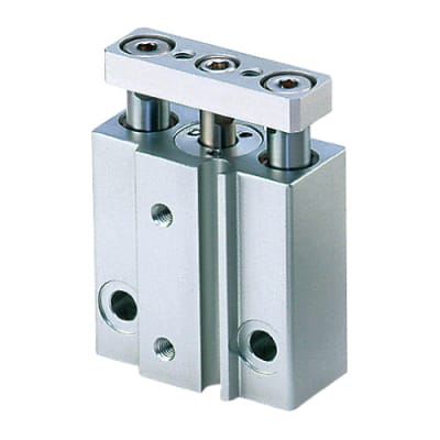
Miniature Guide Rod Cylinder
ø
6,
ø
10
Series MGJ
MGJ
Miniature Guide Rod Cylinder
6 10 F8N
Miniature Guide
Rod Cylinder
Bore size
6
10
6 mm
10 mm
Nil
S
Cylinder stroke (mm)
Refer to the following table q and w.
Number of auto switches
2 pcs.
1 pc.
Auto switch type
Nil
Without auto switch (Built-in magnet)
∗ Select the applicable auto switch from the table below.
∗ The minimum auto switch mounting stroke with 2 auto switches is
4 mm.
6
10
Bore size (mm) Standard stroke (mm)
5, 10, 15
5, 10, 15, 20
Table
q
Standard Strokes
6
10
Example
Bore size (mm) Applicable stroke (mm)
1 to 15 (Spacer type)
1 to 20 (Spacer type)
Model no.: MGJ6-9
Installing a 1 mm width spacer for MGJ6-10
External size: same as MGJ6-10
Table
w
Intermediate Stroke (by the 1 mm stroke)
∗ Lead wire length symbols: 0.5 m
.............
Nil (Example) F8N
3 m
................
L (Example) F8NL
5 m
................
Z (Example) F8NZ
∗ Auto switches marked with 쑗 are produced upon receipt of order.
∗ When using non-applicable auto switches, please consult with SMC.
∗ Auto switch is shipped together (not assembled).
Type
Special
function
Electrical
entry
Indicator
light
Wiring
(output)
Load voltage
DC
Direct
mounting
F8N
F8P
F8B
쎲
쎲
쎲
쎲
쎲
쎲
쑗
쑗
쑗
IC
circuit
Relay
PLC
–
0.5
(Nil)
3
(L)
5
(Z)
Auto switch part no.
Lead wire length (m)
Applicable load
Applicable Auto Switches/
Refer to pages 1719 to 1827 for detailed auto switch specifications.
–
Yes 24 V
5 V
12 V
12 V
3-wire
(NPN)
3-wire
(PNP)
2-wire
Grommet
(Perpen-
dicular)
Solid state switch
256