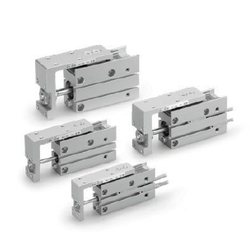
Standard Stroke
Bore size (mm)
6, 10, 16, 20
5, 10, 15, 20, 25, 30, 40, 50, 60
0.3 0.5 0.7
(N)
Standard stroke (mm)
Theoretical Output
Bore size
(mm)
Operating
direction
OUT
IN
OUT
IN
OUT
IN
OUT
IN
28
21
78
66
201
172
314
264
8
6
23
19
60
51
94
79
14
10
39
33
101
86
157
132
19
14
55
46
141
121
220
185
Piston area
(mm
2
)
Operating pressure (MPa)
3
4
6
8
Rod size
(mm)
Specifications
Fluid
Action
Piping port size
Minimum operating pressure
Maximum operating pressure
Proof pressure
Ambient and fluid temperature
Piston speed
Allowable kinetic energy (J)
Lubrication
Cushion
Stroke length tolerance
Air
Double acting
M5 x 0.8
Non-lube
Rubber bumper on both ends
Solid state auto switch D-M9, M9W
Reed auto switch D-A9
+1.0
0
0.7 MPa
1.05 MPa
0.0125 0.025 0.05 0.1
0.15 MPa 0.05 MPa0.06 MPa
Without auto switch: −10 to 70°C
With auto switch: −10 to 60°C
(No freezing)
50 to 500 mm/s
6 10 16 20
Auto switch
(Option)
6
10
16
20
Weight
5 10 15 20 25 30 40 50 60
Stroke (mm)
Model
MXH6
MXH10
MXH16
MXH20
(g)
Low speed cylinder (5 to 50 mm/s)
Special port location
Intermediate stroke (Spacer type)
Fluororubber seal
Machining tapped hole, drilled
hole and pin hole additionally
Symbol
Specifications
-XB13
-XC3
-XC19
-XC22
-XC79
Note) Intermediate strokes are available with “Made to Order” model (-XC19).
(For details, refer to page 1346.)
Made to Order
(Refer to pages 1247 to 1440 for details.)
Symbol
Rubber bumper
61
104
194
352
66
112
204
369
75
125
222
400
80
133
232
417
88
146
250
448
93
153
260
466
107
174
288
514
120
195
316
562
134
216
343
610
Bore size (mm)
20
MXH Series
