-XB11
-XB22
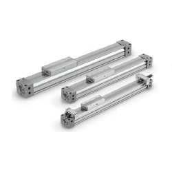
Long stroke
Symbol
Specifications
Shock absorber/
soft type RJ series mounted
Made to Order
Click here for details
-X168
Helical insert thread
Symbol
Specifications
Made to Order: Individual Specifications
(For details, refer to page 1198.)
∗For details about Copper/Fluorine-free Specifica-
tions, refer to the SMC website.
Bore size (mm)
Without stroke adjustment unit
RB2015
58.8
15
1500
25
8.34
20.50
RB1007
5.9
7
1500
70
4.22
6.86
RB1412
19.6
12
1500
45
6.86
15.98
5 to 60
Note 1) Be aware that when the stroke adjustment range is increased with the adjustment bolt,
the air cushion capacity decreases. Also, when exceeding the air cushion stroke ranges
on page 1191, the piston speed should be 100 to 200 mm/s.
Note 2) The piston speed is 100 to 1000 mm/s for centralized piping.
Note 3) Use at a speed within the absorption capacity range. Refer to page 1191.
Note 4) Due to the construction of this product, it may have more fluctuation in operating speed
compared to a rod type air cylinder. For applications that require constant speed, select
the equipment corresponding to the required level.
Stroke adjustment unit
Intermediate
fixing spacer
Spacer length
H unit
Long spacer
∗Spacers are used to fix the stroke adjustment unit an intermediate stroke position
Stroke adjustment unit mounting diagram
Example of H6H7 attachment
Left side
Port Port
H unit
Short spacer
Right side
Right side stroke adjustment unit
Without
unit
With short
spacer
With short
spacer
With short
spacer
With long
spacer
With long
spacer
With long
spacer
A:With adjustment bolt
L:With low load shock
absorber + Adjustment bolt
H:With high load shock
absorber + Adjustment bolt
Without unit
A:With adjustment bolt
L:With low load shock absorber +
Adjustment
bolt
With short spacer
With long spacer
With short spacer
With long spacer
With short spacer
With long spacer
H:With high load shock absorber +
Adjustment
bolt
Nil
AS
A6S
A7S
LS
L6S
L7S
HS
H6S
H7S
SA
A
A6A
A7A
LA
L6A
L7A
HA
H6A
H7A
SA6
AA6
A6
A7A6
LA6
L6A6
L7A6
HA6
H6A6
H7A6
SA7
AA7
A6A7
A7
LA7
L6A7
L7A7
HA7
H6A7
H7A7
SL
AL
A6L
A7L
L
L6L
L7L
HL
H6L
H7L
SL6
AL6
A6L6
A7L6
LL6
L6
L7L6
HL6
H6L6
H7L6
SL7
AL7
A6L7
A7L7
LL7
L6L7
L7
HL7
H6L7
H7L7
SH
AH
A6H
A7H
LH
L6H
L7H
H
H6H
H7H
SH6
AH6
A6H6
A7H6
LH6
L6H6
L7H6
HH6
H6
H7H6
SH7
AH7
A6H7
A7H7
LH7
L6H7
L7H7
HH7
H6H7
H7
Without Spacer
With short spacer
With long spacer
0 to –11.5
–11.5 to –23
–23 to –34.5
0 to –12
–12 to –24
–24 to –36
0 to –16
–16 to –32
–32 to –48
∗Stroke adjustment range is applicable for one side when mounted on a cylinder.
Fluid
Action
Operating pressure range
Proof pressure
Ambient and fluid temperature
Cushion
Lubrication
Stroke length tolerance
Bore size (mm)
Front/Side port
Bottom port
25 32 40
Air
Double acting
0.1 to 0.8 MPa
1.2 MPa
5 to 60°C
Air cushion
Non-lube
2700 or less , 2701 to 5000
Rc1/8 Rc1/4
ø8ø6
Piping port
size
Specifications
Piston Speed
Stroke Adjustment Unit Specifications
Stroke Adjustment Unit Symbol
Shock Absorber Specifications
+2.8
0
+1.8
0
25 to 40
100 to 1000 mm/s
100 to 1000 mm/s
Note 1)
100 to 1500 mm/s
Note 2)
A unit
L unit, H unit
Stroke
adjustment unit
Bore size (mm)
Configuration
Shock absorber model
Unit symbol
25
L
RB1007
+
with
adjustment bolt
With
adjustment bolt
A H
RB1412
+
with
adjustment bolt
32
L
RB1412
+
with
adjustment bolt
With
adjustment bolt
A H
RB2015
+
with
adjustment bolt
40
L
RB1412
+
with
adjustment bolt
With
adjustment bolt
A H
RB2015
+
with
adjustment bolt
Stroke adjustment
range by Intermediate
fixing spacer (mm)
Left side stroke adjustment unit
Shock Absorber Model for L and H Units
Standard
Shock absorber/
soft type (-XB22)
L
H
L
H
RB1007
RB1412
RJ1007H
RJ1412H
RB1412
RB2015
RJ1412H
— —
Type
Stroke
adjustment unit
Bore size (mm)
25 32 40
Max. energy absorption (J)
Stroke absorption (mm)
Max. collision speed (mm/s)
Max. operating frequency (cycle/min)
Operating temperature range (°C)
Spring force
(N)
Extended
Retracted
∗The shock absorber service life is different from that of the MY1B cylinder
depending on operating conditions. Refer to the Series RB Specific
Product Precautions for the replacement period.
Model
MY1B Series
Mechanically Jointed Rodless Cylinder
Basic Type
Symbol
Air cushion
1189