M9NV
M9PV
M9BV
M9NWV
M9PWV
M9BWV
M9NAV
∗
1
M9PAV
∗
1
M9BAV
∗
1
—
—
—
M9N
M9P
M9B
M9NW
M9PW
M9BW
M9NA
∗
1
M9PA
∗
1
M9BA
∗
1
Auto switch model
Perpendicular
ø25 to ø40
ø50, ø63ø16, ø20
ø25 to ø63
ø16, ø20
In-line
—
—
—
—
—
—
—
—
—
—
—
—
—
—
—
—
—
—
—
—
—
—
—
—
A96
A93
A90
Z76
Z73
∗
2
Z80
How to Order
Nil
Without auto switch
(Built-in magnet)
Applicable auto switches
vary depending on the bore
size. Select an applicable one
referring to the table below.
Piping
Standard type
Centralized piping type
Nil
G
Slide bearing guide type
Cam follower guide type
Guide type
M
C
16 mm
20 mm
25 mm
32 mm
40 mm
50 mm
63 mm
Bore size
16
20
25
32
40
50
63
Side seal
With protective cover
None
With side seal
Nil
K
Note) Cylinders with side seal are
available for ø16 to ø40.
Port thread type
Type
M thread
Rc
NPT
G
Bore size
ø16, ø20
Symbol
Nil
TN
TF
ø25, ø32,
ø40, ø50,
ø63
Auto switch
Type
Special
function
—
Grommet 24 V
24 V
3-wire (NPN)
3-wire (PNP)
2-wire
3-wire (NPN)
3-wire (PNP)
2-wire
3-wire (NPN)
3-wire (PNP)
2-wire
3-wire (NPN equivalent)
2-wire
No
Yes
Yes
Grommet
Electrical
entry
Load voltage
Wiring
(Output)
Pre-wired
connector
Applicable load
DC AC
Lead wire length (m)
0.5
(Nil)
1
(M)
5
(Z)
Diagnostic
indication
(2-color
indicator)
Water
resistant
(2-color
indicator)
—
100 V
100 V or less
—
3
(L)
IC circuit
—
IC circuit
—
IC circuit
—
IC circuit
—
IC circuit
—
Relay,
PLC
5 V, 12 V
12 V
5 V, 12 V
12 V
5 V, 12 V
12 V
5 V
12 V
Relay,
PLC
∗ Lead wire length symbols: 0.5 m······Nil (Example) M9NW
1 m······M (Example) M9NWM
3 m·······L (Example) M9NWL
5 m·······Z (Example) M9NWZ
∗ Solid state auto switches marked with “” are produced upon receipt of order.
∗ Separate switch spacers (BMG2-012) are required to retrofit auto switches (M9 type) on
cylinders ø25 to ø63.
∗1Water resistant type auto switches can be mounted on the above models, but in such case SMC cannot guarantee water resistance.
Indicator
light
Solid state auto switch
Reed
auto switch
MY1
M
W
K 300 M9BW32
2 pcs
1 pc
“n” pcs
Number of
auto switches
Nil
S
n
Made to Order Specifications
For details, refer to page 1351.
Stroke adjustment unit symbol
Refer to “Stroke adjustment unit” on page 1351.
Cylinder stroke (mm)
Bore size
(mm)
16, 20, 25, 32
40, 50, 63
Standard stroke (mm)
∗
100, 200, 300, 400, 500, 600, 700
800, 900, 1000, 1200, 1400, 1600
1800, 2000
3000
Maximum
manufacturable
stroke (mm)
∗ The stroke can be manufactured up to the maximum stroke from 1 mm stroke in 1 mm
increments. However, when the stroke is 49 mm or less, the air cushion capability lowers
and multiple auto switches cannot be mounted. Pay special attention to this point.
Also when exceeding a 2000 mm stroke, specify “-XB11” at the end of the model number.
For details, refer to the “Made to Order Specifications”.
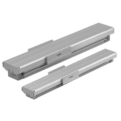
Mechanically Jointed Rodless Cylinder with Protective Cover
Slide Bearing Guide Type, Cam Follower Guide Type
MY1W Series
ø16, ø20, ø25, ø32, ø40, ø50, ø63
Applicable Auto Switches
/Refer to pages 1575 to 1701 for further information on auto switches.
∗ Refer to page 1360 for details on other applicable auto switches than listed above.
∗ For details about auto switches with pre-wired connector, refer to pages 1648 and 1649.
∗ Auto switches are shipped together (not assembled). (Refer to pages 1359 to 1361 for the details of auto switch mounting.)
∗21 m type lead wire is only applicable to D-A93.
1350