Symbol
Rubber bumper (Magnet type)
-XB6
-XB9
-XB11
-XB13
-XC24
-XC57
Head resistant cylinder (–10 to 150
C)
Low-speed cylinder (15 to 50mm/s)
Long stroke type
Low-speed cylinder (7 to 50mm/s)
With magnetic shielding plate
With floating joint
Symbol Specifications
Made to Order
Click here for details
-X116
-X132
-X160
-X168
-X206
-X210
-X322
-X324
-X1468
Hydro specifications
Axial ports
High speed specifications
Helical insert thread specifications
Added mounting tap positions for slider
Non-lubricated exterior specifications
Outside of cylinder tube with hard chrome plating
Non-lubricated exterior specifications (with dust seal)
Interchangeable specification with CY1
6
Symbol Specifications
Air
1.05 MPa
0.7 MPa
–10 to 60
C (No freezing)
50 to 500 mm/s
Rubber bumper
Not required (Non-lube)
0 to 250 st:
+
1.0
, 251 to 1000 st:
+
1.4
, 1001 st to:
+
1.8
Horizontal, Inclined, Vertical
Note)
Standard equipment (accessory)
Fluid
Proof pressure
Max. operating pressure
Min. operating pressure
Ambient and fluid temperature
Piston speed
Cushion
Lubrication
Stroke length tolerance (mm)
Mounting orientation
Mounting nut (2 pcs.)
Magnet holding force (N)
Specifications
Theoretical Cylinder Thrust
0.16 0.16 0.16 0.16 0.15 0.14 0.12 0.12 0.12
ø6, ø10
100
90
80
70
60
50
40
30
20
10
0
0.1 0.2 0.3 0.4 0.5 0.6 0.7 0.8 0.9 1.0
Theoretical thrust (N)
Supply pressure (MPa)
Bore size
ø
10
ø
6
ø15, ø20, ø25, ø32, ø40
1200
0
0.1 0.2 0.3 0.4 0.5 0.6 0.7 0.8 0.9 1.0
Theoretical thrust (N)
Supply pressure (MPa)
1000
900
800
700
500
400
300
200
100
600
1100
ø
40
ø32
ø
25
ø
20
ø
15
ø
40
ø
32
ø
25
ø
20
ø
15
ø50, ø63
3000
2500
2000
1500
1000
500
0
0.1 0.2 0.3 0.4 0.5 0.6 0.7 0.8 0.9 1.0
Theoretical thrust (N)
Supply pressure (MPa)
ø50
Bore size
Bore size
Bore size
ø
63
ø
50
Bore size
ø
63
Bore size ø
10
ø
6
Note) When vertically mounting, it is impossible to perform an intermediate stop by means of a
pneumatic circuit.
6 10 15 20 25 32 40 50 63
19.6 53.9 137 231 363 588 922 1471 2256
Bore size (mm)
0
0
0
Caution
When calculating the actual thr-
ust, design should consider the
minimum actuating pressure.
Unit: kg
Weight
Calculation method/Example: CY3B32-500
Bore size (mm)
Basic weight (at 0 st)
Additional weight per 50 mm of stroke
15
0.275
0.015
10
0.08
0.014
6
0.052
0.004
20
0.351
0.02
25
0.672
0.023
32
1.287
0.033
40
2.07
0.04
50
3.2
0.077
63
5.3
0.096
Basic weight1.287 kg
Additional weight 0.033/50 st
Cylinder stroke500 st
1.287 + 0.033 x 500
50 = 1.617 kg
Made to Order: Individual Specifications
(For details, refer to pages 1480 to 1482.)
CY3B Series
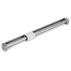
Magnetically Coupled Rodless Cylinder
Basic Type
For clean specifications, refer to “Pneumatic Clean
Series” catalog (CAT.E02-23).
1469
