-XB9
-XB13
Low speed (15 to 50 mm/s)
Ultra low speed (7 to 50 mm/s)
Symbol Specifications
Made to Order
Click here for details
-X116
-X168
-X210
-X322
-X324
-X431
-X2423
Air-hydro
Helical insert thread
Non-lubricated exterior (without dust seal)
Outside of cylinder tube with hard chrome plated
Non-lubricated exterior (with dust seal)
Switch rails on both sides (with 2 pcs.)
Mounting surface tapped hole type
Symbol Specifications
Made to Order: Individual Specifications
(For details, refer to pages 1507 and 1508.)
Bore size (mm) 6 10 15 20 25 32 40
Air
1.05 MPa
0.7 MPa
0.18 MPa
−10 to 60°C (No freezing)
50 to 400 mm/s
Rubber bumper/Shock absorber
Non-lube
19.6 53.9 137 231 363 588 922
0 to 250 st: , 251 to 1000 st: , 1001st or longer:
+1.0
0
+1.4
0
+1.8
0
Fluid
Proof pressure
Maximum operating pressure
Minimum operating pressure
Ambient and fluid temperature
Piston speed
∗
Cushion
Lubrication
Stroke length tolerance (mm)
Magnetic holding force (N)
∗ In the case of setting an auto switch at the intermediate position, the maximum piston speed is
subject to restrict for detection upon the response time of a load (relays, sequence controller,
etc.).
Specifications
Bore size (mm)
6 10 15 20 25 32 40
CY1S
CY1SG
Basic weight
Additional weight for 50 stroke
Basic weight
Additional weight for 50 stroke
Note)
The maximum absorbed energy and maximum operating frequency was measured at ordinary
temperature (approximately 20 to 25°C.)
Calculation: (Example) CY1SG25-500Z
Basic weight (At 0 stroke) … 1.662 kg Additional weight for 50 stroke … 0.178 kg
Cylinder stroke … 500 st
1.662 + 0.178 x 500 ÷ 50 = 3.442 kg
Weights
Bore size
(mm)
Standard stroke (mm)
Maximum
manufacturable
stroke (mm)
50, 100, 150, 200
50, 100, 150, 200, 250, 300
50, 100, 150, 200, 250, 300, 350, 400, 450, 500
100, 150, 200, 250, 300, 350, 400, 450,
500, 600, 700, 800
100, 150, 200, 250, 300, 350, 400, 450,
500, 600, 700, 800, 900, 1000
300
500
750
1000
1500
1500
6
10
15
20
25
32
40
Note 1) Intermediate stroke is available in 1 mm increments. (Produced upon receipt of order)
Note 2)
Minimum stroke available without auto switch or with one auto switch is 15 mm and minimum
25 mm for with 2 auto switches.
Note 3)
For 2 or more auto switches with stroke less than 25 mm (minimum 15 mm), consider
“-X431” (2 switch rails).
Standard Strokes
(kg)
Shock Absorber Specifications
Applicable cylinder
−10 to 60°C (No freezing)
CY1S6
RJ0604
0.5
4
0.05 to 1
80
150
CY1S10
RJ0806H
0.05 to 2
CY1S15
RJ0806L
0.05 to 1
1
6
80
245
CY1S20
RJ1007L
3
7
0.05 to 1
70
422
RJ1412L
10
12
0.05 to 1
45
814
CY1S25 CY1S32
RJ2015H
0.05 to 2
CY1S40
RJ2015L
0.05 to 1
30
15
25
1961
0.231
0.053
0.236
0.050
0.428
0.082
0.435
0.079
0.743
0.111
0.743
0.108
1.317
0.184
1.331
0.176
1.641
0.186
1.662
0.178
2.870
0.284
2.903
0.273
4.508
0.430
4.534
0.411
Shock absorber model
Max. absorbed energy (J)
Stroke absorption (mm)
Collision speed (m/s)
Max. operating frequency (cycle/min)
Max. allowable thrust (N)
Ambient temperature (°C)
Symbol
Rubber bumper
(Magnet type)
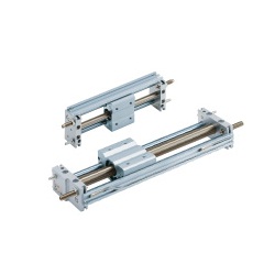
CY1S Series
Magnetically Coupled Rodless Cylinder
Slider Type: Slide Bearing
Made to
Order
1501