R
-XB9
-XB13
-XB22
Low speed cylinder (15 to 50 mm/s)
Low speed cylinder (7 to 50 mm/s)
Shock absorber soft type RJ series type
Symbol Specifications
Made to Order Specifications
Click here for details
-X116
-X168
-X322
-X431
Hydro specifications
Helical insert thread specifications
Outside of cylinder tube with hard chrome plated
Auto switch rails on both side faces (with 2 pcs.)
Symbol Specifications
Symbol
Rubber bumper
(Magnet type)
Air
1.05 MPa
0.7 MPa
0.18 MPa
–10 to 60°C (No freezing)
50 to 500 mm/s
Rubber bumper/Shock absorber
Not required (Non-lube)
0 to 250 st:
+1.0
, 251 to 1000 st:
+1.4
, 1001 st and up:
+1.8
Auto switch mounting rail
Fluid
Proof pressure
Maximum operating pressure
Minimum operating pressure
Ambient and fluid temperature
Piston speed
∗
Cushion
Lubrication
Stroke length tolerance (mm)
Holding force (N)
Standard equipment
6 10 15 20
25
32
40
0.324
–
0.044
0.580
–
0.077
1.10
1.02
0.104
1.85
1.66
0.138
2.21
2.04
0.172
4.36
4.18
0.267
4.83
4.61
0.406
(kg)
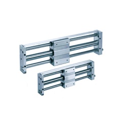
Easy piping and wiring
Hollow shafts are used, and centralization of
ports on one side makes piping easy.
Auto switches can be mounted through the
use of special switch rails.
Shock absorbers and
adjusting bolt are standard
equipment
I
mpacts at stroke end due to high speed use
can be absorbed, and fine adjustment of the
stroke is possible.
Type H
Type L
6 10 15 20 25 32 40
19.6
–
53.9
–
137
81.4
231
154
363
221
588
358
922
569
Bore size (mm)
Bore size (mm)
Number of magnets
CY1L H
CY1L
L
Basic weight
Additional weight per each
50mm of stroke
0.05 to 5
–10 to 80 °C
6
CY1L10
15
Refer to the RB series in Best Pneumatics No. 2-3 for the details on shock absorbers.
Shock absorber model
Maximum energy absorption: (J)
Stroke absorption: (mm)
Collision speed: (m/s)
Max. operating frequency: (cycle/min)
∗
Ambient temperature range
Spring force: (N)
Extended
Retracted
CY1L20 CY1L25 CY1L
32
40
The shock absorber service life is different from that of the CY1L cylinder. Refer to the Specific Product Precautions for the replacement period.
Applicable rodless cylinder
Bore size
(mm)
6
10
15
20
25
32
40
Amount of adjustment by adjusting bolt:
R(
mm)
Single side
6
5.5
3.5
5.5
5
5.5
4.5
Both sides
12
11
7
11
10
11
9
RB0805
0.98
5
80
1.96
3.83
RB1006
3.92
6
70
4.22
6.18
RB1411
14.7
11
45
6.86
15.3
RB2015
58.8
15
25
8.34
20.50
0 0 0
Bore size
(mm)
300
500
50, 100, 150, 200
50, 100, 150, 200, 250, 300
50, 100, 150, 200, 250, 300, 350
400, 450, 500
100, 150, 200, 250, 300, 350
400, 450, 500, 600, 700, 800
900, 1000
6
10
15
20
25
32
40
Standard stroke (mm)
Maximum available
stroke (mm)
100, 150, 200, 250, 300, 350
400, 450, 500, 600, 700, 800
750
1000
1500
1500
CY1L
Plate B Plate A
Adjusting
bolt
Shock
absorbers
Specifications
Calculation
(Example) CY1L32H-500
•Basicweight····4.36kg•Additionalweight······0.267/50st•Cylinderstroke······500st
4.36 + 0.267 x 500 ÷ 50 = 7.03 kg
Standard Stroke
Amount of Adjustment by Adjusting Bolt
∗ In the case of setting an auto switch at the intermediate position, the maximum piston speed is subject
to restrict for detection upon the response time of a load (Relays, Sequence controller, etc.).
∗
Since the cylinder is in an intermediate stop condition when
stroke adjustment is performed, use caution regarding the
operating pressure and the kinetic energy of the load.
∗
The amount of adjustment for adjustment bolts is the
total amount when adjusted on both plate ends. For
the adjustment on a single plate end, the amount of
adjustment is half of the figures in the table above.
∗ Adjust the stroke adjustment with an adjustment
bolt. It cannot be adjusted by a shock absorber.
CY1L Series
Magnetically Coupled Rodless Cylinder
Slider Type: Ball Bushing Bearing
Weight
Shock Absorber Specifications
Note) Intermediate stroke is available in 1 mm increments.
∗ It denotes the values at the maximum energy absorption per one cycle. Therefore, the operating
frequency can be increased according to the energy absorption.
Made to Order: Individual Specifications
(For details, refer to pages 1538 and 1539.)
1517