Series VH
5-8-8
How to Order
VH 2 0 1 02
1(P) port location
R
L
1(P) port 180° location change
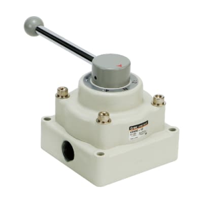
Long handle (Applicable to VH300/400)
Port size (Nominal size)
02
03
04
06
10
1/4
3/8
1/2
3/4
1
Function
0
1
2
3 position closed center
3 position exhaust center
2 position
Thread type
Nil
N
F
Rc
NPT
G
Piping/Mounting
Symbol
0
1
2
3
Piping
Note)
Side
Side
Bottom
Bottom
Mounting method
Body
Panel mounting
Body
Panel mounting
Body size (Base size)
2
3
4
6
1/4 base
3/8 base
1/2 base
1 base
Hand valve
VH200
VH300
VH400
VH600
0.9
0.7
0.5
2000
0.1
0.2
0.3
0.4
0.5
0.6
0.7
0.8
0.1
0.2
0.3
0.4
0.4
0.1
0.2
0.3
0.4
0.5
0.6
4000 6000
0.6
0.7
0.8
0.9
0.1
0.2
0.3
10 15
0.5
0.6
1.0
1000
0.6
0.9
0.1
0.2
0.3
0.4
0.5
0.6
0.7
0.8
0.7
0.1
0.2
0.3
0.4
0.5
1.0
1.0
2000
0.7
0.8
0.9
1.0
Valve output pressure (MPa)
Valve output pressure (MPa)
Valve output pressure (MPa)
Effective area S = 7.5 mm
2
Effective area S = 20 mm
2
Effective area S = 194 mm
2
Effective area S = 55 mm
2
Supply pressure MPaSupply pressure MPaSupply pressure MPa
Supply pressure MPaSupply pressure MPa
Supply pressure MPaSupply pressure MPa
Flow rate ( /min (ANR))
Flow rate ( /min (ANR))
Flow rate (m
3
/min (ANR))
0.8
0.9
Valve output pressure (MPa)
200 400
0.1
0.2
0.3
0.4
0.5
0.6
0.7
0.8
0.1
0.2
0.3
0.4
0.5
0.6
0.7
1.0
600 800 1000
0.9
1.0
Supply pressure MPaSupply pressure MPaSupply pressure MPa
Flow rate ( /min (ANR))
000
05
Flow Characteristics
Note) Only side piping is available for
VH200 and VH600 and R port
is located on the bottom.
∗ When specifying more than one option, indicate
symbols alphabetically.