Precautions
Mounting
Warning
Specifications
Basic type, Flange type, Foot type
Mounting
Operating range
JA
3-050
4-070
5-080
6-100
8-125
10-125
14-150
18-150
22-150
26-150
30-150
36-150
M3 x 0.5
M4 x 0.7
M5 x 0.8
M6 x 1
M8 x 1.25
M10 x 1.25
M14 x 1.5
M18 x 1.5
M22 x 1.5
M26 x 1.5
M30 x 1.5
M36 x 1.5
40F 14-150
6
10
10, 15
20
25, 32
40
50, 63
80
100
125, 140
160
180
200
Model/Specifications
None
Be sure to read this before handling
the products. Refer to back page 50
for Safety Instructions.
Operating
pressure
Pneumatic cylinder:
1 MPa or less
Hydraulic cylinder:
3.5 MPa or less
Center of sphere
Axial
center
Operating
range
1.
To screw the male threads of the rod into the female threads of
the socket or the case, make sure that it does not bottom out.
If the floating joint is used with its rod bottom out, the stud will
not be able to float, causing damage.
For the screw-in depth of the female threads, refer to the
dimensions (page 1146). As a rule, after the rod bottoms out,
back off 1 to 2 turns.
2. The dust cover may adhere to the stud. In this case,
move the dust cover at the neck of the stud by the
finger or twist the stud slightly left or right to break in
the dust cover before use.
Additionally, when screwing the stud and socket or
the case into a driven body, screw in such parts with
the dust cover removed. When screwing in such
parts without removing the dust cover, this may
cause damage to the dust cover.
3.
To use a floating joint to connect the cylinder rod to a
driven body, secure it in place by applying a torque that is
appropriate for the thread size. Also, if there is a risk of
loosening during operation, take measures to prevent
loosening, such as using a locking pin or thread adhesive.
In the event that the connected portion becomes loose,
the driven body might lose control or fall off, leading to
equipment damage or injury to personnel.
4.
This product is not a rotary joint. So, the product cannot
be used for rotational or rotation acting applications.
5. Be sure to use the cushion mechanism of the cylinder
or the buffer mechanism, such as the shock absorber
so that any impact force is not applied to the floating
joint when stopping a driven body. If there is no buffer
mechanism, an excessive impact force is generated.
As a result, the tensile compression force of the
floating joint may exceed its maximum level.
How to Order
Mounting type
Nil
F
L
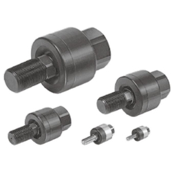
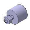
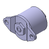
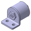
Basic type
Flange type
Foot type
Applicable bore size (mm)
Symbol
Applicable
bore size
(mm)
Model
Standard
Thread nominal size
(Standard)
Nominal
thread size
Applicable cylinder
nominal thread size
Option
X11
Nil
High temperature
specifications
–5 to 100°C
Floating Joint: Standard Type
JA Series
RoHS
Maintenance
Warning
1. Do not reuse if disassembled.
High strength adhesive is applied to the portion of the
connection that is threaded to prevent it from
loosening, and it must not be disassembled. If it is
forcefully disassembled, it could lead to damage.
JA series
Made to Order: Individual
Specifications -X530
Note) For details, refer to page
1149.
For pneumatic cylinders
6
10
15
20
30
40
63
80
100
140
160
180
200
Model
Applicable
bore size
(mm)
Applicable
cylinder
nominal
thread size
Rotating
angle
Ambient
temperature
Allowable
eccentricity
U (mm)
Maximum operating tension
and compression force (N)
Basic type
Flange type
Foot type
Standard/Thread nominal size
Semi-standard/Thread nominal size
JA6-3-050
JA10-4-070
JA15-5-080
JA15-6-100
JA20-8-125
JA30-10-125
JA40-14-150
JA63-18-150
JA80-22-150
JA
100-26-150
JA
140-30-150
JA
160-36-150
6
10
10, 15
15
20
25, 32
40
50, 63
80
100
125, 140
160
M3 x 0.5
M4 x 0.7
M5 x 0.8
M6 x 1
M8 x 1.25
M10 x 1.25
M14 x 1.5
M18 x 1.5
M22 x 1.5
M26 x 1.5
M30 x 1.5
M36 x 1.5
19
54
123
123
1100
2500
4400
11000
18000
28000
54000
71000
–
–
–
–
1100
2500
4400
11000
18000
28000
36000
55000
–
–
–
–
1000
2000
4400
9000
14000
22000
36000
55000
0.5
0.5
0.5
0.5
0.5
0.5
0.75
1
1.25
2
2.5
3
JA20-8-100
JA25-10-150
JA32-10-100
JA40-12-125
JA40-12-150
JA40-12-175
JA50-16-150
JA63-16-200
JA80-20-250
JA
100-24-300
JA
100-27-150
JA
125-27-200
JA
160-33-200
20
25
32
32, 40
40
32, 40
50
50, 63
80
100
100
125
160
M8 x 1
M10 x 1.5
M10 x 1
M12 x 1.25
M12 x 1.5
M12 x 1.75
M16 x 1.5
M16 x 2
M20 x 2.5
M24 x 3
M27 x 1.5
M27 x 2
M33 x 2
1100
2500
2500
4400
4400
4400
11000
11000
18000
28000
28000
28000
71000
1100
2500
2500
4400
4400
4400
11000
11000
18000
28000
28000
28000
55000
1000
2000
2000
4400
4400
4400
9000
9000
14000
22000
22000
28000
55000
0.5
0.5
0.5
0.75
0.75
0.75
1
1
1.25
2
2
2
3
±5°
±5°
-5 to 60°C
1. The black zinc chromate treatment is applied to
the material surfaces of the case, flange and foot.
However, the white deposit may rarely occur on
the surface. This white deposit does not affect the
product functions. However, if the white deposit
becomes a problem from a viewpoint of appear-
ance, special products with the surface treatment
changed to the electroless nickel plating are also
available. For details, please contact SMC.
Caution
1144