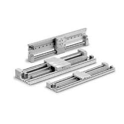
Shock Absorber Specifications
Standard Stroke
Magnetic Holding Force
-XB10
-XB11
Specifications
Bore size (mm)
Fluid
Lubrication
Action
Maximum operating pressure (MPa)
Min. operating pressure (MPa)
Proof pressure (MPa)
Ambient and fluid temperature (°C)
Piston speed (mm/s)
Cushion
Stroke length tolerance (mm)
Stroke adjustment movable range (mm)
Piping type
Port size
Note 1)
Note 2)
10 15 25
Air
Non-lube
Double acting
0.7
0.2
1.05
10 to 60 (No freezing)
50 to 500
Built-in shock absorber
Centralized piping
0 to 250st:
+1.0
0
251 to 1000st:
+1.4
0
1001st to:
1.4 to 0.6
Rc 1/8
1.2 to 0.8
M5 x 0.8
+1.8
0
Note 1) The stroke adjustment movable range in the above table is that for the standard
adjustment bolt. For more information, please refer to page 1559.
Note 2) With ø25, piping screws can be selected by the customer. (Refer to “How to Order”.)
Shock absorber model
Max. energy absorption (J)
Stroke absorption (mm)
Max. impact speed (m/s)
Max. operating frequency (cycle/min)
Spring force (N)
Weight (g)
When extended
When retoacted
Applicable bore size (mm)
Note 1)
25
RB1006-X552
3.92
6
70
4.22
6.18
25
10, 15
RB0805-X552
0.98
5
80
1.96
3.83
15
0.05 to 5
Note 1) Represents the maximum absorption energy per cycle. Thus, the operation frequency
can be increased with the absorption energy.
Note 2) The shock absorber service life is different from that of the CY1F cylinder depending on
operating conditions. Refer to the Specific Product Precautions for the replacement
period.
Bore size
(mm)
10
15
25
Standard stroke (mm)
50, 100, 150, 200, 250, 300
50, 100, 150, 200, 250, 300, 350, 400, 450, 500
100, 150, 200, 250, 300, 350, 400, 450, 500, 550, 600
500
750
1200
Maximum manufacturable
stroke (mm)
∗The stroke is available in 1 mm increments with the maximum stroke as the upper limit.
For a stroke in the standard stroke range, suffix the part number with -XB10. If the
stroke does not fall within the standard stroke range, suffix the part no. with -XB11.
Refer to the Made to Order Specifications on pages 1733 and 1739.
Bore size (mm)
Magnetic holding force
10
53.9
15
137
25
363
Unit: N
Symbol Specifications
Intermediate stroke (Using exclusive body)
Long stroke
Made to Order Specifications
Click here for details
1552
CY1F Series
A
