How to Order
5 V
12 V
5 V, 12 V
——
—
—
Y69A
Y7PV
Y69B
Y7NWV
Y7PWV
Y7BWV
Z76
Z73
Z80
Y59A
Y7P
Y59B
Y7NW
Y7PW
Y7BW
—
쎲
쎲
쎲
쎲
쎲
쎲
쎲
쎲
쎲
쎲
쎲
쎲
쎲
쎲
쎲
쎲
쎲
쎲
—
쎲
—
쑗
쑗
쑗
쑗
쑗
쑗
—
100 V
100 V or less
5 V, 12 V
5 V , 12 V
12 V
12 V
—
24 V
24 V
AC
DC
0.5
(Nil)
3
(L)
—
5
(Z)
CYP
15
Z73
15
32
15 mm
32 mm
Number of auto switches
Nil
S
n
Auto switch
Standard stroke
Bore size
200
Nil
L
R
S
Piping port location
a
b
c
d
e
f
g
h
15, 32
100, 150, 200, 250, 300, 350
400, 450, 500, 600, 700
Piping Port Locaition
LRS
a
b h
g
dc fe
Bore size (mm)
Standard stroke (mm)
2 pcs.
1 pc.
“n” pcs.
Operating direction: Right
Operating direction: Left
Operating direction: Right
Operating direction: Left
Operating direction: Right
Operating direction: Left
Operating direction: Right
Operating direction: Left
Note) Plugs are installed in ports other than those indicated for the model.
Nil
Operating direction
←Left Right→
Reed switch
Solid state
switch
Type
Electrical
entry
Indicator
light
Wiring
(Output)
Load voltage
Perpendicular
In-line
Auto switch model
Electrical entry direction
Lead wire length (mm)
∗
Applicable load
IC circuit
—
IC circuit
IC circuit
IC circuit
—
IC circuit
Relay,
PLC
Relay,
PLC
3-wire
2-wire
3-wire (NPN)
3-wire (PNP)
2-wire
3-wire (NPN)
3-wire (PNP)
2-wire
Yes
No
Yes
Grommet
Grommet
—
—
Special
function
Diagnostic
indication
(2-color indication)
∗ Lead wire length symbols: 0.5 m ········· Nil (Example) Y69B
3 m ········· L Y69BL
5 m ········· Z Y69BZ
∗∗ Auto switches marked with a “쑗” symbol are produced upon receipt of order.
Applicable Auto Switch/Refer to page 8-30-1 for further information on auto switches.
Nil
Without auto switch
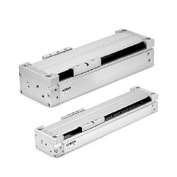
Clean Room Rodless Cylinder
Series CYP
ø15, ø32
For the applicable auto switch
model, refer to the table below.
Note 1) Please consult with SMC if the maximum
stroke is exceeded.
Note 2) Intermediate strokes are available as a
special order.
8-17-7
MX쏔
MTS
MY쏔
CY쏔
MG쏔
CX쏔
D-
-X
20-
Data