Bore size (mm)
125 140 160
Bore size (mm)
125 140 160
Lube
Fluid
Proof pressure
Max. operating pressure
Min. operating pressure
Piston speed
Cushion
Stroke length tolerance
Mounting
Cylinder Specifications
Not required (Non-lube)
Air
1.57 MPa
0.97 MPa
0.08 MPa
50 to 500 mm/s
∗
Air cushion
Without auto switch: 0 to 70°C (No freezing)
With auto switch: 0 to 60°C (No freezing)
Ambient and
fluid temperature
∗ Load limits exist depending upon piston speed when locked, mounting direction and operating pressure.
Locking action
Unlocking pressure
Lock starting pressure
Operating pressure range
Locking direction
Holding force (kN)
Spring locking (Exhaust lock)
0.25 MPa or more
0.20 MPa or less
0.25 to 0.7 MPa
Both directions
Bore size
(mm)
Tube material
125, 140
160
Cylinder Stroke
Aluminum alloy Carbon steel pipe
Up to 1000
Up to 1200
Up to 1000
Up to 1200
Up to 1600
Up to 1600
Lock type
Spring locking
Piston speed (mm/s)
100
±0.5
300
±1.0
500
±2.0
8.4 10.5 13.8
Condition: Lateral, Supply pressure P = 0.5 MPa
Load mass ······ Upper limit of allowed value
Solenoid valve for locking ···· Mounted directly to unlocking port
Maximum value of stopping position dispersion from 100 measurements
Basic style, Head side flange style,
Single clevis style, Double clevis style,
Center trunnion style
Basic style, Head side flange style,
Single clevis style, Double clevis style,
Center trunnion style
Basic style, Head side flange style,
Single clevis style, Double clevis style,
Center trunnion style
Foot style,
Rod side flange style
Bore size
(mm)
125, 140
160
Cylinder Stroke/Auto Switch Mounting
on Cylinder Unit (Built-in Magnet)
Up to 1000
Up to 1200
Up to 1400
Up to 1400
Foot style, Rod side flange style
∗ Be sure to make cylinder selections in accordance with the method given on page 758.
JIS Symbol
—XA쏔
—XC14
Change of rod end shape
Change of trunnion bracket mounting position
Symbol
Specifications
Refer to the minimum auto switch mounting
stroke (page 774) for those with an auto switch.
Refer to pages 773 to 775 for cylinders with
auto switches.
• Minimum auto switch mounting stroke
• Proper auto switch mounting position
(detection at stroke end) and mounting height
• Operating range
• Switch mounting bracket: Part no.
(mm)
(mm)
(mm)
761
Series CNS
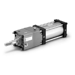
Cylinder with Lock
Double Acting, Single Rod
Made to Order Specifications
(For details, refer to pages 1836 and 1844.)
Up to 250: , 251 to 1000: , 1001 to 1500: , 1501 to 1600:
+1.0
0
+1.4
0
+1.8
0
+2.2
0
Basic style, Axial foot style, Rod side flange style,
Head side flange style, Single clevis style, Double clevis style,
Center trunnion style
Lock Specifications
Stopping Accuracy