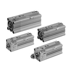
Compact Cylinder with Air Cushion and Lock
ø32, ø40, ø50, ø63
Series RLQ
How to Order
Bore size
32
40
50
63
32 mm
40 mm
50 mm
63 mm
Cylinder stroke (mm)
Refer to “Standard Stroke” on page 845.
Body option
Nil
M
Standard (Rod end female thread)
Rod end male thread
RLQ
RDLQ
B
B
32
32
50
50
M
M
F
F
Port thread type
Nil
TN
TF
Rc
NPT
G
Bypass piping
Nil
None
(Emergency
stop)
R
With bypass piping,
right-hand piping
(Drop prevention)
L
With bypass piping,
left-hand piping
(Drop prevention)
∗ The right and left indicate the piping directions viewed from
the front.
∗ When no by-pass piping is used (when the product is used
for emergency stops), solenoid valves for unlocking are
necessary.
∗ For detailed information, please refer to "Pneumatic Circuit"
in Specific Product Precautions on page 841.
Applicable Auto Switch/Refer to pages 1719 to 1827 for detailed auto switch specifications.
∗ Lead wire length symbols: 0.5 m ·········· Nil (Example) M9NW
1 m ·········· M (Example) M9NWM
3 m ·········· L (Example) M9NWL
5 m ·········· Z (Example) M9NWZ
None ·········· N (Example) J79CN
∗ Solid state auto switches marked with a “
쑗
” are produced upon receipt of order.
∗ Besides the models in the above table, there are some other auto switches that are applicable. For more information, refer to page 861.
∗ Refer to pages 1784 and 1785 for the details of auto switches with a pre-wired connector.
∗ When mounting D-A9쏔(V)/M9쏔(V)/M9쏔W(V)/M9쏔A(V)L types on a side other than the port side as for bore 32 to 50, order auto switch mounting brackets separately. Refer to
page 860 for details.
∗ When mounting brackets (foot/head side flange/double clevis style) are used, then in some cases auto switches cannot be retrofitted.
No
Yes
No
Yes
Yes
Yes
Type Special function
Electrical
entry
direction
Grommet
Connector
Grommet
Connector
Grommet
Grommet
—
200 V
100 V
100 V or less
—
24 V or less
—
Wiring
(output)
3-wire
(NPN equiv.)
2-wire
3-wire (NPN)
3-wire (PNP)
2-wire
3-wire (NPN)
3-wire (PNP)
2-wire
3-wire (NPN)
3-wire (PNP)
2-wire
4-wire
Load voltage
DC
24 V
24 V
5 V
—
12 V
5 V, 12 V
12 V
5 V, 12 V
—
5 V,
12 V
12 V
5 V,
12 V
12 V
5 V,
12 V
12 V
5 V, 12 V
AC
Lead-wire length (m)
쎲
쎲
쎲
쎲
쎲
쎲
쎲
쎲
쎲
쎲
쎲
쎲
쎲
쎲
쑗
쑗
쑗
쎲
쎲
쎲
쎲
쎲
쎲
쎲
쎲
쎲
쎲
쎲
쎲
쎲
쎲
쎲
쎲
쎲
쎲
쎲
—
—
—
—
쎲
쎲
—
쑗
쑗
쑗
쎲
쑗
쑗
쑗
쑗
쑗
쑗
쑗
—
—
—
—
쎲
쎲
—
—
—
—
쎲
—
—
—
—
—
—
—
—
—
—
—
—
—
—
쑗
쑗
쑗
—
쑗
쑗
쑗
쑗
쑗
쑗
쑗
—
Applicable load
Pre-wired
connector
IC circuit
—
IC circuit
—
IC circuit
—
IC circuit
—
IC circuit
—
IC circuit
—
IC circuit
A96V
A72
A93V
A90V
A73C
A80C
A79W
M9NV
M9PV
M9BV
J79C
M9NWV
M9PWV
M9BWV
M9NAV
M9PAV
M9BAV
—
0.5
(Nil)
3
(L)
5
(Z)
None
(N)
1
(M)
—
—
—
—
—
—
—
쎲
쎲
쎲
—
쎲
쎲
쎲
쑗
쑗
쑗
—
—
—
Auto switch model
Perpendicular
A96
A72H
A93
A90
—
—
—
M9N
M9P
M9B
—
M9NW
M9PW
M9BW
M9NA
M9PA
M9BA
F79F
In-line
Diagnostic indication (2-color display)
Diagnostic indication
(2-color display)
Water resistant
(2-color display)
With diagnostic output (2-color display)
—
—
Relay
PLC
Relay
PLC
With auto switch
With auto switch
(Built-in magnet)
Mounting style
B
A
L
F
G
D
Through-hole (Standard)
Both ends tapped style
Foot style
Rod flange style
Head flange style
Double clevis style
Built-in Magnet Cylinder Model
If a built-in magnet cylinder without an
auto switch is required, there is no need
to enter the symbol for the auto switch.
(Example) RDLQL40-50-B
Locking direction
F
B
Extension locking
Retraction locking
M9BW
Auto switch
Nil
Without auto switch
∗
For the applicable auto switch
model, refer to the table below.
2 pcs.
1 pc.
“n” pcs.
Number of
auto switches
Nil
S
n
∗ Mounting brackets are shipped
together (not assembled).
Indicator light
Solid state switch
Reed switch
844