Tube material
Nominal pressure (MPa)
Bore size (mm)
Auto switch mounting
Model
Action
Fluid
Nominal pressure (MPa)
Model
Piston speed
Cushion
Models
Specifications
CH2E
Aluminum alloy
3.5
Applicable
CH2E
CH2F
Stainless steel
7
Applicable
CH2G
Steel
14
—
CH2H
Stainless steel
14
Applicable
32, 40, 50, 63, 80, 100
Maximum
allowable pressure (MPa)
Minimum
operating pressure (MPa)
Ambient and
fluid temperature
Proof pressure (MPa)
CH2F
CH2G
CH2H
Double acting/Single rod
Hydraulic fluid
3.5 7 14
Head: 9
Rod: B rod 13.5
: C rod 11
Head: 18
Rod: B rod 18
: C rod 14
3.5
5.0
10.5 21
Head: 0.15
Rod: 0.2
Without auto switch: –10 to 80°C
With auto switch: –10 to 60°C
8 to 300 mm/s
Cushion seal type
Stroke length tolerance
to 100 st , 101 to 250 st , 251 to 630 st ,
631 to 1000 st , 1001 to 1800 st
+0.8
0
+1.25
0
+1.0
0
+1.4
0
+1.8
0
Note) Refer to page 214 for definitions of terms related to pressure.
32, 40, 50
63
80, 100
B
(Basic type)
LA, LB
(Foot type)
FA, FB, FC
FD, FY, FZ
(Flange type)
CA, CB
(Single clevis type)
TC
(Center trunnion type)
Standard Strokes
Port and Cushion Valve Positions
Standard strokes (mm)
Mounting
type
Position
Symbol
Nil A C D E F G H
Port: Top
Cushion valve:
Right
Port: Right
Cushion valve:
Bottom
: Piping port
∗ The cylinder's exterior dimensions represented here are as seen from the rod end of the cylinder.
: Cushion valve
Port: Left
Cushion valve:
Top
Port: Top
Cushion valve:
Left
Port: Top
Cushion valve:
Bottom
Port: Right
Cushion valve:
Top
Port: Right
Cushion valve:
Left
Port: Left
Cushion valve:
Right
Long stroke (mm)
25 to 800
25 to 800
25 to 1000
1800 (1401 or more with tie-rod reinforcing ring)
Note 2)
1800 (1501 or more with tie-rod reinforcing ring)
Note 3)
1800
Cylinder bore size (mm)
Symbol Specifications
-XA
-XC14
Note 1)
Refer to pages 230 and 231, to determine stroke limitation depending on the type of mounting brackets that will be
used. Then make yur selection. Long stroke ranges also differ depending on the type of mounting brackets.
Note 2) The long stroke range for the CH2E, CH2F, and CH2H series with flange and clevis type mounting brackets as
well as the CH2G series is up to 1400 mm.
Note 3) The long stroke range for the CH2E, CH2F, and CH2H series with flange and clevis type mounting brackets as
well as the CH2G series is up to 1500 mm.
Change of rod end shape
Change of trunnion bracket mounting position
Rod Sizes
B-series
C-series
40
22.4
18
32
18
—
50
28
22.4
63
35.5
28
80
45
35.5
100
56
45
Rod size
series
∗
Bore size
(mm)
(mm)
Accessories (Option)
∗ Based on JIS B8367.
Note) Maximum operating temperature:
Nylon tarpaulin (60°C),
Neoprene cloth (110°C)
∗ Refer to page 375 for part numbers and dimensions.
(For rod boot, refer to the dimensions.)
(Front and rear sides)
Cushion Strokes
Bore size (mm)
Effective cushion stroke
(mm)
40
16
32
16
50
17
63
16
80
20
100
23
Single knuckle, Double knuckle, Lock
nut, Knuckle pin, Rod boot (Nylon
tarpulin, Neoprene cloth)
Note)
∗ Consult with SMC.
Hydraulic Fluid Compatibility
Standard mineral hydraulic fluid
W/O hydraulic fluid
O/W hydraulic fluid
Water/Glycol hydraulic fluid
Phosphate hydraulic fluid
Compatibility
Compatible
Compatible
Compatible
∗
Not compatible
Hydraulic fluid
Made to order specifications
(For details, refer to page 382)
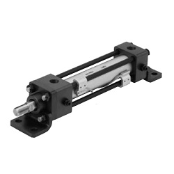
CH2E/CH2F/CH2G/CH2H Series
JIS Standard Hydraulic Cylinder
Double Acting/Single Rod
359