CHA 40 100L
L
CHDA 40 100 M9BW
Cylinder stroke (mm)
Refer to the standard stroke table on
page 397.
Made to Order specifications
For details, refer to page 397.
How to Order
∗ Lead wire length symbols: 0.5 m ······ Nil (Example) M9NW
1 m ······ M (Example) M9NWM
3 m ······ L (Example) M9NWL
5 m ······ Z (Example) M9NWZ
∗ Since there are applicable auto switches other than listed, refer to page 413 for details.
∗ For details about auto switches with pre-wired connector, refer to pages 474 and 475.
∗ D-A9, M9, M9W, M9A auto switches are shipped together (not assembled). (Only auto switch mounting brackets are packed assembled.)
∗1 Water resistant type auto switches can be mounted on the above models, but in such case SMC cannot guarantee water resistance.
Consult with SMC regarding water resistant types with the above model numbers.
∗ Solid state auto switches marked "" are produced upon receipt of order.
∗∗ Types D-G5, K59, G5W, K59W, G5BA, G59F, G5NT, B5, B64, and B59W
cannot be mounted on ø63 bore size cylinders.
Applicable Auto Switches/Refer to pages 431 to 490 for further details on each auto switch.
Pre-wired
connector
3-wire (NPN equiv.)
2-wire
Load voltage Auto switch model
100 V
100 V or less
100 V, 200 V
200 V or less
100 V, 200 V
AC
DC
Lead wire length (m)
Applicable
load
5 V
12 V
24 V
Yes
No
Yes
No
Yes
Yes
3-wire (NPN)
3-wire (PNP)
2-wire
3-wire (NPN)
2-wire
3-wire (NPN)
3-wire (PNP)
2-wire
3-wire (NPN)
3-wire (PNP)
2-wire
4-wire (NPN)
Reed auto switch Solid state auto switch
A96
A93
A90
A54
A64
A59W
B54
∗∗
B64
∗∗
A33
A34
A44
B59W
∗∗
Relay
PLC
Relay
PLC
Relay
PLC
24 V
24 V
Grommet
Terminal
conduit
DIN terminal
Grommet
Grommet
Terminal
conduit
Grommet
Tie-rod mount Band mount
5 V, 12 V
12 V
5 V, 12 V
12 V
5 V, 12 V
12 V
5 V, 12 V
12 V
5 V, 12 V
M9N
M9P
M9B
M9NW
M9PW
M9BW
M9NA
∗
1
M9PA
∗
1
M9BA
∗
1
F59F
G59
∗∗
G5P
∗∗
K59
∗∗
G39
K39
G59W
∗∗
G5PW
∗∗
K59W
∗∗
G5BA
∗∗
G59F
∗∗
Type
Electrical
entry
Indicator
light
Wiring
(output)
Special function
0.5
(Nil)
1
(M)
3
(L)
5
(Z)
None
Diagnostic
indication
(2-color indicator)
Water resistant
(2-color indicator)
Diagnostic output (2-color indicator)
Diagnostic indication (2-color indicator)
IC circuit
IC circuit
IC circuit
IC circuit
IC circuit
IC circuit
IC circuit
PLC
With auto switch
(built-in magnet)
With Auto Switch
Without Auto Switch
Aluminum alloy
Steel tube
Nil
F
Tube material
Bore size
40
50
63
80
100
125
160
40 mm
50 mm
63 mm
80 mm
100 mm
125 mm
160 mm
Aluminum tube
Steel tube
∗ Indicate in alphabetical order.
Cylinder options
Nil
J
K
Nil
N
R
H
Without rod boot
Nylon tarpaulin
Neoprene cloth
Both sides
Without cushion
With rod cushion
With head cushion
Rod boot
Cushion
Number of
auto switches
2 pcs.
1 pc.
3 pcs.
"n" pcs.
Nil
S
3
n
Without auto switch
Nil
Auto switch type
∗ Select applicable auto switch
models from the table below.
Bore size
40
50
63
80
100
40 mm
50 mm
63 mm
80 mm
100 mm
Aluminum tube
Mounting type
B
L
F
G
C
D
T
U
Basic type
Axial foot type
Rod flange type
Head flange type
Single clevis type
Double clevis type
Center trunnion type
Rod trunnion type
Built-in Magnet
Cylinder Model
If a built-in magnet cylinder
without auto switch is required,
there is no need to enter the
symbol for the auto switch.
(Example) CHDAB50-100
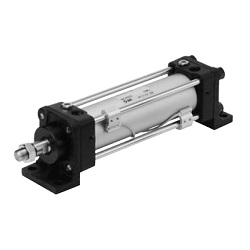
Tie-rod Type Hydraulic Cylinder
Double Acting/Single Rod
CHA Series
ø40, ø50, ø63, ø80, ø100, ø125, ø160
3.5 MPa
396