How to Order
Cylinder stroke (mm)
∗ Refer to page 1202 for standard strokes.
RHC 20B
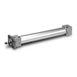
High Power Cylinder
M9BW
Bore size
20
25
32
40
50
63
80
100
20mm
25mm
32mm
40mm
50mm
63mm
80mm
100mm
High power cylinder
Nil
S
n
2 pcs.
1 pc.
“n” pcs.
Number of auto switches
Auto switch
Nil
Without auto switch (Built-in magnet)
∗ For the applicable auto switch model, refer
to the table below.
Mounting style
B
L
F
G
Basic style
Axial foot style
Rod side flange style
Head side flange style
Nil
TN
Rc
NPT
Port type
∗ Since there are other applicable auto switches than listed, refer to page 1214 for details.
∗ For details about auto switches with pre-wired connector, refer to pages 1784 and 1785.
∗ D-A9쏔/M9쏔/M9쏔W auto switches are shipped together (not assembled). (Only auto switch mounting brackets are assembled before shipped.)
Made to Order
Refer to page 1202 for
details.
Type Special function
Electrical
entry
Grommet
Connector
Terminal
conduit
DIN terminal
Grommet
Connector
Grommet
Grommet
—
100V
100 V or less
100V, 200V
200 V or less
—
24 V or less
—
100V, 200V
—
Wiring
(Output)
3-wire
(NPN equivalent)
2-wire
3-wire (NPN)
3-wire (PNP)
2-wire
3-wire (NPN)
3-wire (PNP)
2-wire
4-wire (NPN)
Load voltage
DC
24V
24V
5V
12V
—
5V, 12V
12V
5V, 12V
12V
5V, 12V
AC
Lead wire length (m)
0.5
(Nil)
쎲
쎲
쎲
쎲
쎲
쎲
쎲
—
—
—
쎲
쎲
쎲
쎲
쎲
쎲
쎲
쎲
쎲
쎲
쎲
쎲
쎲
쎲
—
쎲
3
(L)
쎲
쎲
쎲
쎲
쎲
쎲
쎲
—
—
—
쎲
쎲
쎲
쎲
쎲
쎲
쎲
쎲
쎲
쎲
쎲
쎲
쎲
쎲
쎲
쎲
1
(M)
—
—
—
—
—
—
—
—
—
—
—
쎲
—
쎲
—
쎲
—
—
쎲
—
쎲
—
쎲
—
—
—
5
(Z)
—
—
—
쎲
—
쎲
쎲
—
—
—
—
쑗
쑗
쑗
쑗
쑗
쑗
쎲
쑗
쑗
쑗
쑗
쑗
쑗
쑗
쑗
None
(N)
—
—
—
—
—
쎲
쎲
쎲
쎲
쎲
—
—
—
—
—
—
—
쎲
—
—
—
—
—
—
—
—
—
—
—
—
—
—
—
—
—
—
—
쑗
쑗
쑗
쑗
쑗
쑗
—
쑗
쑗
쑗
쑗
쑗
쑗
쑗
쑗
Applicable load
Pre-wired
connector
IC circuit
—
IC circuit
—
IC circuit
—
IC circuit
—
IC circuit
—
IC circuit
Relay,
PLC
Relay,
PLC
PLC
Relay,
PLC
A96
A93
A90
C73C
C80C
M9N
—
M9P
—
M9B
—
H7C
M9NW
—
M9PW
—
M9BW
—
H7BA
H7NF
—
—
—
—
—
—
G59
—
G5P
—
K59
—
—
G59W
—
G5PW
—
K59W
G5BA
G59F
B54
B64
A33
A34
A44
B59W
—
—
—
Auto switch model
Applicable bore size (mm)
ø20 to ø63
ø80, ø100
Diagnostic indication (2-color indication)
Diagnostic indication
(2-color indication)
Applicable Auto Switch/Refer to pages 1719 to 1827 for further information on auto switches.
High Power Cylinder
ø20, ø25, ø32, ø40, ø50, ø63, ø80, ø100
Series RHC
Yes YesNoNoNo
YesYes
Yes
Reed switch Solid state switch
With diagnostic output (2-color indication)
Water resistant (2-color indication)
∗ Solid state auto switches marked with “
쑗
” are produced upon receipt of order.
∗ D-A9쏔V/M9쏔V/M9쏔WV/D-M9쏔A(V)L types cannot be mounted.
∗ Do not indicate suffix “N” for no lead wire on D-A3쏔/A44/G39/K39 models.
∗ Lead wire length symbols: 0.5 m··········Nil (Example) M9NW
1 m·········· M (Example) M9NWM
3 m·········· L (Example) M9NWL
5 m·········· Z (Example) M9NWZ
None ·········· N (Example) H7CN
Indicator light
1201