Mounting Bracket Part No.
RZQ 32 200
100
A
Number of auto switches
Mounting bracket
A
B
L
F
G
D
Both ends tapped
Through-hole
Foot style
Rod side flange style
Head side flange style
Double clevis style
Bore size
32
40
50
63
32 mm
40 mm
50 mm
63 mm
Thread type
Nil
TN
TF
Rc
NPT
G
Nil
S
n
2 pcs.
1 pc.
"n" pcs.
First-stage stroke
Refer to "Standard Stroke".
Auto switch
∗ For the applicable auto switch model, refer to
the table below.
Nil
Without auto switch (Built-in magnet)
Applicable Auto Switch/Refer to pages 1719 to 1827 for detailed auto switch specifications.
∗ Lead wire length symbols: 0.5 m ·········· Nil (Example) M9NW
1 m ·········· M (Example) M9NWM
3 m ·········· L (Example) M9NWL
5 m ·········· Z (Example) M9NWZ
None ·········· N (Example) J79CN
∗ Auto switches marked with a "" symbol are produced upon receipt of order.
∗ D-P4DWL is available in sizes ø40 to ø63.
∗ Only D-P4DW type is assembled at the time of shipment.
No
Yes
No
Yes
Yes
Yes
Type Special function
Electrical
entry
Grommet
Connector
Grommet
Connector
Grommet
Grommet
Indicator light
—
200 V
100 V
100 V or less
—
24 V or less
—
Wiring
(output)
3-wire
(NPN Equiv.)
2-wire
3-wire (NPN)
3-wire (PNP)
2-wire
3-wire (NPN)
3-wire (PNP)
2-wire
3-wire (NPN)
3-wire (PNP)
2-wire
4-wire
2-wire (Non-polar)
Load voltage
DC
24V
24V
5 V
—
12 V
5 V, 12 V
12 V
5 V, 12 V
—
5 V,
12 V
12 V
5 V,
12 V
12 V
5 V,
12 V
12 V
5 V, 12 V
—
AC
Lead wire length (m)
0.5
(Nil)
3
(L)
5
(Z)
None
(N)
—
Applicable load
Pre-wired
connector
IC circuit
—
IC circuit
—
IC circuit
—
IC circuit
—
IC circuit
—
IC circuit
—
IC circuit
—
Relay,
PLC
Relay,
PLC
A96V
A72
A93V
A90V
A73C
A80C
A79W
M9NV
M9PV
M9BV
J79C
M9NWV
M9PWV
M9BWV
M9NAV
M9PAV
M9BAV
—
—
1
(M)
—
—
Auto switch model
Perpendicular
A96
A72H
A93
A90
—
—
—
M9N
M9P
M9B
—
M9NW
M9PW
M9BW
M9NA
M9PA
M9BA
F79F
P4DW
In-line
Diagnostic indication (2-color indication)
With diagnostic output (2-color indication)
Magnetic field resistant (2-color indication)
—
—
M9BW
∗ Full stroke is 75 mm or less in the case of RZQB
(through-hole type).
Full stroke
Refer to "Standard Stroke".
Bore size (mm)
32
40
50
63
Foot
Note 1)
RZQ-L032
RZQ-L040
RZQ-L050
RZQ-L063
Flange
RZQ-F032
RZQ-F040
RZQ-F050
RZQ-F063
Double clevis
Note 2)
RZQ-D032
RZQ-D040
RZQ-D050
RZQ-D063
Note 1) When ordering foot brackets, order two pieces per cylinder.
Note 2) The following parts are included with each mounting bracket.
Foot, Flange/Body mounting bolts
Double clevis/Clevis pins, type C retaining ring for axis, Body mounting bolts
Reed switch Solid state switch
Diagnostic indication
(2-color indication)
Water resistant
(2-color indication)
∗ In addition to the models in the above table, there are some other auto switches that are applicable. For more information, refer to page 1230.
∗ Refer to pages 1784 and 1785 for the details of auto switches with a pre-wired connector.
∗ When D-A9(V)/M9(V)/M9W(V)/M9A(V)L types with ø32 to ø50 are mounted on a side other than the port side, order auto switch mounting brackets separately. Refer to
page 1230 for details.
1219
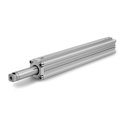
How to Order
3 Position Cylinder
Series RZQ
ø32, ø40, ø50, ø63