10, 20, 30, 40, 50
10, 20, 30, 40, 50, 75
10, 20, 30, 40, 50, 75, 100
10, 20, 30, 40, 50, 75, 100, 125
10, 20, 30, 40, 50, 75, 100, 125, 150
10, 20, 30, 40, 50, 75, 100, 125, 150
ø6
ø8
ø12
ø16
ø20
ø25
Bore size (Stroke (mm))
MXQR 12 50 M9BWJ
L
Port thread type
Nil
TN
TF
M thread
Rc
NPT
G
ø6 to ø16
ø20, ø25
Adjuster options
None
Adjuster
(Rubber
stopper)
Shock
absorber
(RB)
Adjuster
(Metal
stopper)
Shock
absorber
RJ
Note 1, 2)
(Short
stroke type)
None
Adjuster (Rubber stopper)
Shock absorber (RB)
Adjuster (Metal stopper)
Shock absorber RJ
Note 1, 2)
(Short stroke type)
Retraction stroke end
Nil
AS
BS
CS
JS
AT
A
BSAT
CSAT
JSAT
BT
ASBT
B
CSBT
JSBT
CT
ASCT
BSCT
C
JSCT
JT
ASJT
BSJT
CSJT
J
Made to Order
Refer to page 2 for details.
2 pcs.
1 pc.
“n” pcs.
Nil
S
n
Number of auto switches
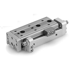
Air Slide Table/
Reversible Type
Applicable Auto Switches/Refer to Best Pneumatics No. 3 for further information on auto switches.
A96V
A93V
A90V
M9NV
M9PV
M9BV
M9NWV
M9PWV
M9BWV
A96
A93
A90
M9N
M9P
M9B
M9NW
M9PW
M9BW
3-wire
(NPN equivalent)
—
24 V
24 V
2-wire
3-wire (NPN)
3-wire (PNP)
2-wire
3-wire (NPN)
3-wire (PNP)
2-wire
Load voltage
Wiring
(Output)
DC AC
—
100 V
100 V or less
—
IC circuit
—
IC circuit
IC circuit
—
IC circuit
—
—
Relay,
PLC
Relay,
PLC
—
—
5 V
12 V
5 V,12 V
12 V
5 V,12 V
12 V
L
Left side Right side
Nil
Adjuster position set
at the time of shipment
∗ The adjuster position can be selected from two choices,
right side and left side. It can be changed on site to suit the
installation conditions. For detailed dimensions, refer to the
product drawing. For the procedure for changing the
position, refer to the MXQR Operation Manual.
Adjuster
Table
Adjuster
Table
Note 1) The shock absorber RJ (short stroke type) is a soft and short stroke type shock
absorber (RJ쏔). For the buffer time, refer to front matter 3. For details of the shock
absorber (RJ), refer to its catalog.
Note 2) The shock absorber (short stroke type) is not available with the MXQR6.
Ye s
No
Ye s
Indicator light
Type Special function
Electrical
entry
Reed auto
switch
Solid state
auto switch
Diagnostic indication
(2-color indication)
Grommet
Grommet
Auto switch model
Lead wire length (m)
Perpendicular
In-line
0.5
(Nil)
5
(Z)
1
(M)
3
(L)
Pre-wired
connector
Applicable
load
How to Order
Auto switch
Nil
Without auto switch (Built-in magnet)
∗ For applicable auto switch models, refer to
the below table.
∗ Lead wire length symbols: 0.5 m ········· Nil (Example) M9NW
1 m ·········· M (Example) M9NWM
3 m ·········· L (Example) M9NWL
5 m ·········· Z (Example) M9NWZ
∗ Solid state auto switches marked with “ ” are produced upon receipt of order.
∗ Since there are other applicable auto switches than listed, refer to page 26 for details.
∗ For details about auto switches with pre-wired connector, refer to pages 1784 and 1785 of Best Pneumatics No. 3.
∗ Auto switches are shipped together, (but not assembled).
Extension stroke end
∗
1
ø6, ø8, ø12, ø16, ø20, ø25
Series MXQR
Air Slide Table/Reversible Type