N
W
V
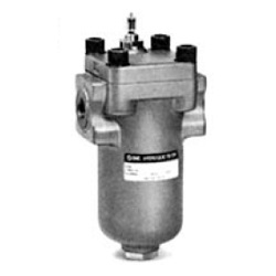
Line Filter
FH34/44/54/64 Series
Replacement Element Part No. (Including O-ring for element)
Port size
03
(
3/8
B
),
04
(
1/2
B
)
06
(
3/4
B
),
08
(
1
B
)
10
(
1 1/4
B
),
12
(
1 1/2
B
)
16
(
2
B
)
20
(
2 1/2
B
),
24
(
3
B
)
5
µ
m
EP910-005N
EP020-005N
EP120-005N
EP220-005N
EP820-005N
10
µ
m
EP910-010N
EP020-010N
EP120-010N
EP220-010N
EP820-010N
20
µ
m
EP910-020N
EP020-020N
EP120-020N
EP220-020N
EP820-020N
Element size
ø55
x 90
ø74
x 117
ø74
x 195
ø88
x 282
ø119
x 280
Note 1) The symbol at the end of the element part no. indicates the hydraulic fluid type.
N: Petroleum, V: Phosphoric ester, W: Water-glycol, Emulsion (10 µm only)
Note 2) Refer to page 528 for micromesh elements.
Note 3) Above elements require one element per filter.
FH
033 40 0 0 0 P 005
Hydraulic filter
3
4
5
6
3.5 MPa
7 MPa
14 MPa
21 MPa
Operating pressure (Max.)
0
1
With relief valve
None
Relief valve
Hydraulic fluid
0
1
2
Petroleum
Water-glycol, Emulsion
Phosphoric ester
005
010
020
5 µm
10 µm
20 µm
Nominal
filtration
P
M
∗
Paper
Micromesh
Element
L
40
42
∗
41
Threaded
Flange
Construction/Connection
∗ Indicates 42 for 3.5 MPa, Port
sizes 3/4 and 1.
0
1
2
4
∗
5
∗
None
Differential pressure indicator
Differential pressure indication switch
Note)
Differential pressure indicator
Differential pressure indication switch
Note)
Differential pressure
indication
L
Nil
IN left
IN right
Fluid direction
Symbol
03
04
06
08
10
12
16
20
24
Threaded Rc
3/8
1/2
3/4
1
1 1/4
1 1/2
—
—
—
Flange SSA
—
15
(
1/2
B
)
20
(
3/4
B
)
25
(
1
B
)
32
(
1 1/4
B
)
40
(
1 1/2
B
)
50
(
2
B
)
65
(
2 1/2
B
)
80
(
3
B
)
Port size
Note) For selection from thread and
flange, refer to “Model/Rated
Flow Rate” on page 510.
How to Order
Note) Click here for details
Note)
The paper elements for water-glycol
or emulsion is 10 µm only.
Note) N.C. and N.O. common
Made to Order
Nil
X0
None (Standard)
Micromesh element equipped
Element upward
removal
Element upward
removal
Blanking cap
Hexagon socket
head cap screw
Cover
Case
Element
w
O-ring
e
O-ring
q
O-ring
r
O-ring
Drain plug
IN
Differential pressure
indication switch
DRAIN
OUT
Differential
pressure
indicator
Relief valve
Differential pressure
indicator
Construction/Seal List
∗ The micromesh element
is a made to order
specification (X0).
Note) N, W and V refer to the hydraulic fluid
symbol indicated at the end of the
element part number.
∗ Construction 42 only
Port
size
03 to 04
06 to 08
03 to 04
06 to 08
10 to 12
16
20 to 24
03 to 04
06 to 08
03 to 04
06 to 08
10 to 12
16
20 to 24
Applicable
hydraulic
fluid
FH340
FH34
FH44 to 64
FH44 to 64
FH34 to 64
FH341 to 641
FH441
FH340
FH34
FH44 to 64
FH44 to 64
FH34 to 64
FH341 to 641
FH441
Applicable
hydraulic
fluid
Petroleum,
Water-glycol,
Emulsion
Phosphoric
ester
Material
NBR-90
FKM-90
Material
NBR-70-1
FKM-70
q O-ring
order no.
(Nominal size)
KA00617
(G80)
KA00611
(G105)
KA00615
(G65)
KA00618
(G90)
KA00611
(G105)
KA00612M
(G145)
KA01296M
(G80)
KA02476
(G105)
KA01759
(G65)
KA02477
(G90)
KA02476
(G105)
KA01760
(G145)
w O-ring
order no.
(Nominal size)
KA00630
(P28)
KA00631M
(P28)
e O-ring
order no.
(Nominal size)
KA00468
(P22A)
KA00079
(P32)
KA00074
(P20)
KA00079
(P32)
KA00803
(P40)
KA00806
(P50)
KA00809
(P85)
KA00713
(P22A)
KA00720
(P32)
KA00102
(P20)
KA00720
(P32)
KA00722
(P40)
KA00636
(P50)
KA00725
(P85)
r O-ring
order no.
(Nominal size)
KA00471
(P30)
KA00082
(P44)
KA00471
(P30)
KA00082
(P44)
KA00806
(P50)
KA00809
(P85)
KA00104
(P30)
KA00107
(P44)
KA00104
(P30)
KA00107
(P44)
KA00636
(P50)
KA00725
(P85)
Replacement O-ring/Seal List (One each of the seal
and O-ring types listed below are required per filter.)
Note) The material and nominal size notations are based on JISB2401.
511