Made to Order
(For details, refer to pages 148 to 155.)
Symbol Specifications
-XA
Change of rod end shape
-XB6
Heat-resistant cylinder (−10 to 150°C)
-XC4
With heavy duty scraper
-XC7
Tie-rod, tie-rod nut, etc. made of
stainless steel
-XC10
Dual stroke cylinder/Double rod type
-XC11
Dual stroke cylinder/Single rod type
-XC22
Fluororubber seal
-XC35
With coil scraper
-XC65
Made of stainless steel
(Combination of -XC7 and -XC68)
-XC68
Made of stainless steel
(with hard chrome plated piston rod)
-XC88
Spatter-resistant coil scraper, Lube-retainer,
grease for welding (Piston rod: Stainless steel 304)
-XC89
Spatter-resistant coil scraper, Lube-retainer,
grease for welding (Piston rod: S45C)
Refer to pages 145 and 146 for cylinders with
auto switches.
· Auto Switch Proper Mounting Position
(Detection at stroke end)
· Minimum Stroke for Auto Switch Mounting
· Operating Range
· How to Mount and Move the Auto Switch
Precautions
Bore size [mm]
32 40 50 63 80 100
Action Double acting
Fluid Air
Proof pressure 1.5 MPa
Max. operating pressure
1.0 MPa
Min. operating pressure
0.05 MPa
Ambient and fluid
temperature
Without auto switch: –20 to 70°C (No freezing)
With auto switch: –10 to 60°C (No freezing)
Lubrication Not required (Non-lube)
Operating piston speed
50 to 1000 mm/s
Allowable stroke
tolerance
Up to 500 stroke:
+2
0
, 501 to 1000 stroke:
+2.4
0
,
1001 to 1500 stroke:
+2.8
0
, 1501 to 2000 stroke:
+3.2
0
Cushion Air cushion on both ends + Bumper cushion
Port size G 1/8 G 1/4 G 1/4 G 3/8 G 3/8 G 1/2
Mounting
Basic, Axial foot, Rod flange,
Head flange, Single clevis, Double clevis
Specifications
Standard Strokes
Intermediate strokes are available.
*1 Please consult with SMC for longer strokes.
Accessories
* Do not use a rod end (or floating joint) together with a single clevis with a ball joint (or clevis
pivot bracket with a ball joint).
* Refer to pages 137 to 140 for dimensions and part numbers of the accessories.
Mounting Basic Foot
Rod
flange
Head
flange
Single
clevis
Double
clevis
Standard
Rod end nut
V V V V V V
Clevis pin
— — — — —
V
Option
Rod end
V V V V V V
Rod clevis
V V V V V V
Rod boot
V V V V V V
Bore size
[mm]
Standard stroke
[mm]
Max.
stroke
*
1
32 25, 50, 80, 100, 125, 160, 200, 250, 320, 400, 500 2000
40 25, 50, 80, 100, 125, 160, 200, 250, 320, 400, 500 2000
50 25, 50, 80, 100, 125, 160, 200, 250, 320, 400, 500, 600 2000
63 25, 50, 80, 100, 125, 160, 200, 250, 320, 400, 500, 600 2000
80 25, 50, 80, 100, 125, 160, 200, 250, 320, 400, 500, 600, 700, 800 2000
100 25, 50, 80, 100, 125, 160, 200, 250, 320, 400, 500, 600, 700, 800 2000
Be sure to read this before handling the products. Refer to page 219 for
safety instructions. For actuator and auto switch precautions, refer to
the “Handling Precautions for SMC Products” and the “Operation
Manual” on the SMC website: http://www.smcworld.com
130
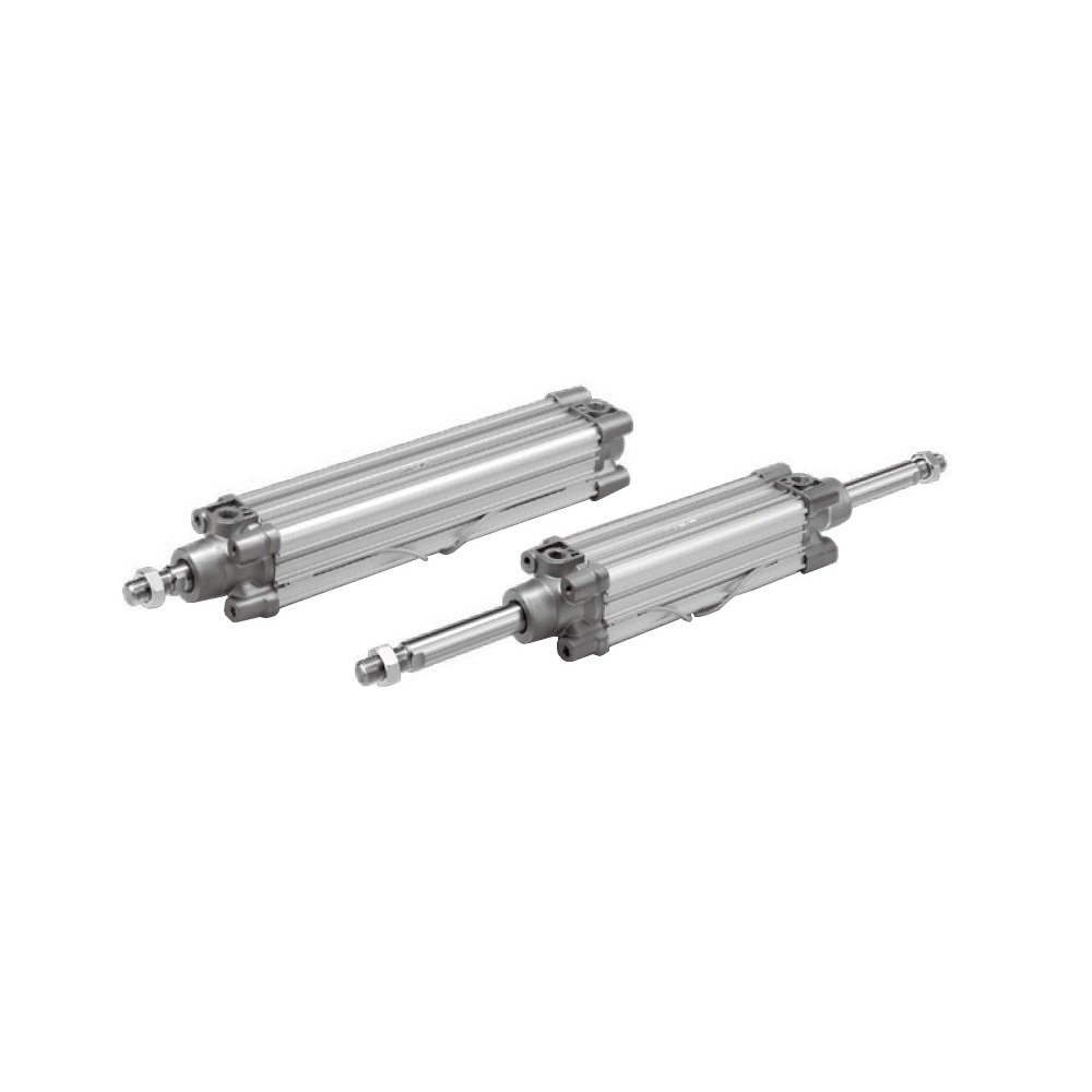
ISO Standard (15552)
Air Cylinder: Standard Type
Double Acting, Single/Double Rod
CP96 Series