Symbol
Nil
A
B
C
D
E
F
G
H
J
K
L
M
N
O
P
Q
R
Pressure display
Note 1, 2)
Supply block type
Note 3)
Supply block mounting position
Note 1) Pressure display means a pressure gauge or digital pressure switch is attached.
When choosing to attach a digital pressure switch is chosen for attachment, be sure to enter the
symbol, referring to table 8, “Digital Presure Switch Output Specifications”. Otherwise, a
pressure gauge will come with the regulator.
Note 2) Pressure gauges are not compatible with copper-free and fluorine-free specifications.
Note 3) Pressure switches are not available with the oil-free specification.
5. Accessories
Symbol
Without
pressure
display
With
pressure
display
Common
supply
block
Common
supply
block with
pressure
switch
3-way
valve
common
supply
block
3-way valve
common
supply block
+
Pressure
switch
block
L side
(Left)
R side
(Right)
B side
(Both)
Digital pressure switch:
with unit switching (MPa is initially set.)
Display unit for product name plate
and pressure gauge: MPa
Display unit for product name plate
and pressure gauge: psi
ZA
Note 1) This option is available for use outside Japan only.
(The SI unit has to be used in Japan.) Additionally,
the pressure switch offers dual unit presentation in
MPa and psi.
Note 2) The digital pressure switch is equipped with unit
switching and initially set to psi.
Note 3) This option is available with the digital pressure
switch. A lead wire with connector (2 m) is included.
Note 1) A pressure gauge with a full span of 0.4 MPa is attached.
Note 2) The oil-free specification is grease-free in the fluid contact area.
Symbol
Nil
Z
7. Unit Representation
Description
None
NPN open collector
PNP open collector
Note) When a digital pressure switch is
attached, the “pressure display” in table 5
“Accessories” will be equipped.
The electrical entry is positioned on the side
opposite the knob.
Symbol
Nil
N
P
8. Digital Presure Switch
Output Specifications
Note)
Details
Manifold (Regulator block, Common supply block, 3-way valve common supply block)
Direct acting
Diaphragm regulator
Relief type
Non-relieving type
Within (Unbalance type)
ø6, ø8, ø10, ø1/4, ø5/16, ø3/8
ø4, ø6, ø5/32, ø1/4
1.5 MPa
1.0 MPa
0.05 to 0.7 MPa
0.05 to 0.35 MPa (Low pressure type)
Air
5 to 60°C
Regulator construction
Working principal
Relief mechanism
Backflow function
Note 1)
IN side tubing O.D.
OUT side tubing O.D.
Proof pressure
Maximum operating pressure
Set pressure range
Fluid
Ambient and operating fluid temperature
Note 2)
Standard
Optional
Standard
Optional
Note 1) 0.1 MPa or greater set pressure is required when used in the reverse flow.
Note 2) 5 to 50°C when the digital pressure switch will be used.
Specifications
Symbol
Nil
1
2
3
4
5
6
7
None
6. Semi-standard
0.35 MPa
setting
Note 1)
Non-
relieving
Oil-free
Note 2)
Common supply
block
Common supply
block with
pressure switch
3-way valve
common
supply block
3-way valve common
supply block
+
Pressure switch
block
With
pressure
guage
With digital
pressure
switch
With
pressure display
Without
pressure display
Refer to pages 734 and 736 for the digital pressure switch and pressure switch specifications.
Note 1, 2)
Note 1, 3)
L side L side
L side L side
Note) A standard model is equipped
with a backflow function. Main
valve opens when the inlet
pressure is released, and then
the outlet pressure backflows
into the inlet side.
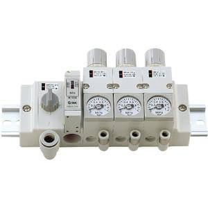
ARM11A Series
Compact Manifold Regulator
Common Supply Type
OUT
IN
2
OUT
2
1
717