10, 20, 30
20, 30, 50
30, 50, 75
30, 50, 75, 100
ø8
ø12
ø16
ø20
Nil
S
n
MXF 12 50 M9BW
ø8
ø12
ø16
ø20
8
12
16
20
MXF A 16 X11
Nil
X11
X12
5 mm
15 mm
25 mm
27
∗ Lead wire length symbols: 0.5 m ················· Nil (Example) M9NW
1 m ················· M (Example) M9NWM
3 m ················· L (Example) M9NWL
5 m ················· Z (Example) M9NWZ
A96V
A93V
A90V
M9NV
M9PV
M9BV
M9NWV
M9PWV
M9BWV
A96
A93
A90
M9N
M9P
M9B
M9NW
M9PW
M9BW
3-wire
(NPN equivalent)
—
24 V
24 V
2-wire
No
3-wire (NPN)
3-wire (PNP)
2-wire
3-wire (NPN)
3-wire (PNP)
2-wire
DC AC
Perpendicular
In-line
0.5
(Nil)
5
(Z)
—
100 V
100 V or less
—
—
—
—
—
—
—
1
(M)
—
—
—
—
—
Diagnostic indication
(2-color indication)
5 V
12 V
5 V,12 V
12 V
5 V,12 V
12 V
3
(L)
How to Order
Made to Order
Refer to page 137 for details.
2 pcs.
1 pc.
“n” pcs.
Number of
auto switches
∗ For the applicable auto switch model, refer to the table below.
Auto switch
Nil
Without auto switch (Built-in magnet)
Bore size/
Stroke (mm)
How to Order Stroke Adjusting Bolt (Accessory)
Applicable
bore size
Adjustment range
Standard
Option
∗ -X12 (adjustable range 25 mm) is not available in Series MXF8/MXF12.
Applicable Auto Switch/Refer to pages 1719 to 1827 for the detailed specifications of auto switches.
Special functionType
Electrical
entry
Wiring
(Output)
Load voltage
Auto switch model
Lead wire length (m)
Applicable
load
Pre-wired
connector
Indicator light
IC
circuit
IC
circuit
IC
circuit
IC circuit
Relay,
PLC
Relay,
PLC
—
—
—
—
Ye sYe s
Grommet
Grommet
Reed
switch
Solid state switch
∗ Solid state auto switches marked with “ ” are produced upon receipt of order.
∗ Since there are other applicable auto switches than listed, refer to page 145 for details.
∗ For details about auto switches with pre-wired connector, refer to pages 1784 and 1785.
∗ Auto switches are shipped together (not assembled).
136
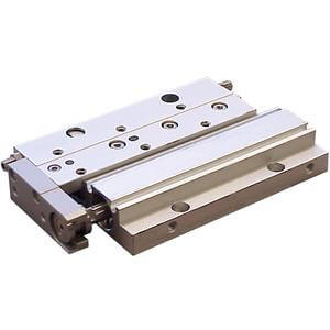
Low Profile Slide Table
Series MXF
Low Profile Slide Table