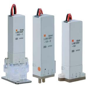
Compact Direct Operated
2/3 Port Solenoid Valve for Chemicals
Series LVM09/090
How to Order
Specifications
LVM 09R3 5 A
(Symbol 1)
IN
(Symbol 2)
OUT
(Symbol 3)
IN
(Symbol 2)
OUT
3
1
2
Symbol
Symbol
Valve type
Number
of ports
09R3
2
N.C.
09R4
N.O.
095R
3 Universal
Diaphragm
EPDM
FKM
Kalrez
®
Wetted part material
Symbol
Plate
PEEK
PEEK
PEEK
A
B
C
Lead wire
length
Nil
150 mm
300 mm
600 mm
3
6
∗ Nil cannot be selected
in the case of function
Y1.
Function
Nil
Standard
With power-saving circuit
Y1
CE compliant
Nil
None
CE compliant
Q
Note 1) Select an appropriate material for the wetted part when fluid such as a cleaning solvent is used. Also, be sure to confirm the fluid compatibility in advance.
Note 2) Indicates the pressure which does not generate breakage, cracks or external leakage after a one-minute airtight test.
Note 3) Indicates the volume of clearance inside the valve chamber after the volume of the diaphragm is subtracted.
Note 4) Since the body (orifice shape) is designed to eliminate residual liquid, mounting in a vertical direction with the coil at the top is recommended. When
residual liquid is not considered, any mounting orientation is available.
Note 5) When the response speed is regarded as important, prevent negative fluctuation of the voltage by adequate regulation.
Note 6) The value is based on SMC’s measurement conditions. The noise level will vary with conditions.
Note 7) Refer to 10 in “Design and Selection” on the back of page 2, if the valve is to be energized continuously for extended periods of time.
Valve construction
Valve type
Number of ports
Fluid
Note 1)
Operating pressure range
Orifice diameter
Response time
Leakage
Proof pressure
Note 2)
Ambient temperature
Fluid temperature
Volume of valve chamber
Note 3)
Mounting orientation
Note 4)
Enclosure
Weight
Rated voltage
Allowable voltage fluctuation
Note 5)
Type of coil insulation
Power consumption
(When rated voltage
is at 24 V)
Standard
With
power-
saving
circuit
Inrush
Holding
Coil switching noise
Note 6)
Diaphragm type direct operated poppet (Rocker type)
2
N.C. N.O.
Air, Water, Pure water, Diluent, Cleaning solvent
–75 kPa to 0.2 MPa
1.1 mm
10 ms or less (at pneumatic pressure)
Zero leakage, either external or internal (at water pressure)
0.3 MPa
0 to 50°C
0 to 50°C (with no condensation)
18 µl
Free
IP40 or equivalent
20 g
12, 24 VDC
±10% of rated voltage
Class B
50 dB
2 W
(0.08 A)
3.3 W
(0.14 A)
0.9 W
Universal
3
Model
LVM09R3 LVM09R4 LVM095R
Base mounted
Flow Characteristics
∗ The values of Av and Cv are based on JIS B 2005:1995,
C and b are based on JIB B 8390:2000.
Av
0.43 x 10
–6
Cv
0.018
C
0.06
b
0.2
Water Air
Coil voltage
5
6
24 VDC
12 VDC
Symbol
Voltage
Base Mounted
1
