JIS Symbol
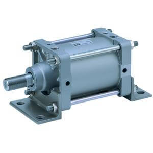
Double acting
Foot
∗
Flange
Single clevis
Double clevis
∗∗
Bore size (mm)
125
CS2-L12
CS2-F12
CS2-C12
CS2-D12
140
CS2-L14
CS2-F14
CS2-C14
CS2-D14
160
CS2-L16
CS2-F16
CS2-C16
CS2-D16
∗ Order two foot brackets per cylinder.
∗∗
When ordering the double clevis style, the clevis pin and 2 split pins are included as accessories.
125
140
160
Mounting
bracket
Bore size
1000 or less
1600 or less
Maximum stroke
Basic, Head flange,
Single clevis, Double clevis,
Center trunnion
Foot, Rod flange
(mm)
• Minimum stroke for auto switch mounting
•
Auto switch proper mounting position
(detection at stroke end) and its mounting
height
• Operating range
• Auto switch mounting bracket part no.
For the specifications of cylinders with auto-
switch, please refer to pages 21 to 24.
-XA첸
-XC3
-XC14
-XC15
-XC26
-XC27
-XC30
-XC68
-XC86
Change of rod end shape
Special port position
Change of trunnion bracket mounting position
Change of tie-rod length
With rod end bracket
Symbol
Specifications
1200 or less
BasicMounting
Center
trunnion
Double
clevis
Single
clevis
Head
flange
Rod
flange
Standard
equipment
Clevis pin
Rod end nut
Single knuckle joint
Rod boot
Foot
Option
Double knuckle joint
(Knuckle pin,
Split pin)
Double clevis pin and double knuckle pin
made of stainless steel
Made of stainless steel
(With hard chrome plated piston rod)
Double clevis pin/Double knuckle pin with
split pin and flat washer
Double acting, Single rod
Air
Bore size (mm)
125 140 160
Action
Fluid
Proof pressure
Maximum operating pressure
Minimum operating pressure
Piston speed
Cushion
Ambient and fluid temperature
Lubrication
Mounting
Stroke length tolerance (mm)
1.57 MPa
0.97 MPa
0.05 MPa
50 to 500 mm/s
Air cushion
Not required (Non-lube)
Stroke
250 or less
251 to 1000
1001 to 1500
1501 to 1600
Basic, Foot, Rod flange, Head flange,
Single clevis, Double clevis, Center trunnion
Tolerance
+1.8
0
+2.2
0
+1.0
0
+1.4
0
Without auto switch
With auto switch
0 to 70°C (No freezing)
0 to 60°C (No freezing)
Specifications
Maximum Stroke
Accessory
Mounting Bracket Part No.
Made to Order Specifications
(For details, refer to pages 25 to 29.)
Rod Boot Material
∗ Maximum ambient temperature for the rod boot itself.
J
K
Nylon tarpaulin
Heat resistant tarpaulin
Symbol
Material
Max. ambient
temperature
70°C
110°C
∗
∗
If using the rod end nut with a single knuckle joint or a double knuckle joint, use the type with
rod end bracket (-XC86) or refer to page 11.
Rod side trunnion mounted on the front
of the rod cover
Basic Double Rod Type Smooth Cylinder Auto Switch Made to Order
3
Air Cylinder
Series CS2