JIS Symbol
Double acting,
Single rod
Specifications
20 25 32 40
0.27 JRubber bumper 0.4 J 0.65 J 1.2 J
0.54 J
(11.0)
0.78 J
(11.0)
1.27 J
(11.0)
2.35 J
(11.8)
Pneumatic
Double acting, Single rod
Air
1.5 MPa
1.0 MPa
0.05 MPa
Standard Stroke
20
25
32
40
25, 50, 75, 100, 125, 150
200, 250, 300
1000
1500
2000
2000
—XA
—XB6
—XB7
—XB9
—XB12
—XB13
—XC3
—XC4
—XC5
—XC6
—XC8
—XC9
—XC10
—XC11
—XC12
—XC13
—XC20
—XC22
—XC25
—XC27
—XC29
—XC35
—XC52
Air cushion
(Effective cushion length (mm))
Bore size (mm)
Rod Boot Material
(mm)
Boss-cut style
Made to Order Specifications
(For details, refer to pages 1373 to 1498.)
Change of rod end shape
Heat resistant cylinder (150 )
Cold resistant cylinder
Low speed cylinder (10 to 50 mm/s)
External stainless steel cylinder
Low speed cylinder (5 to 50 mm/s)
Special port location
With heavy duty scraper
Heat resistant cylinder (110 )
Piston rod and rod end nut made of stainless steel
Adjustable stroke cylinder/Adjustable extension type
Adjustable stroke cylinder/Adjustable retraction type
Dual stroke cylinder/Double rod type
Dual stroke cylinder/Single rod type
Tandem cylinder
Auto switch mounting rail style
Head cover axial port
Fluororubber seals
No fixed orifice of connecting port
Double clevis pin and double knuckle pin made of stainless steel
Double knuckle joint with spring pin
With coil scraper
Mounting nut with set screw
Symbol
Specifications
Type
Action
Fluid
Proof pressure
Maximum operating pressure
Minimum operating pressure
Ambient and fluid temperature
Lubrication
Stroke length tolerance
Piston speed
Cushion
Allowable
kinetic energy
Not required (Non-lube)
Rubber bumper: 50 to 750 mm/s, Air cushion: 50 to 1000 mm/s
Rubber bumper, Air cushion
Bore size
(mm)
Maximum stroke
(mm)
Note 1) Other intermediate strokes can be manufactured upon receipt of order.
Manufacture of intermediate strokes at 1 mm intervals is possible.
(Spacers are not used.)
Note 2) When exceeding 300 strokes, the allowable maximum stroke length is
determined by the stroke selection table (front matter 28).
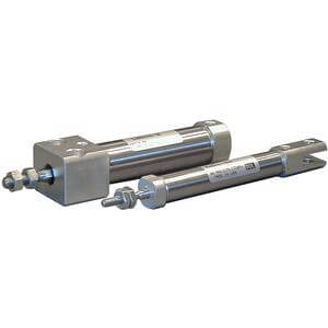
Clevis integrated
With air cushion
Boss for the head side cover bracket
is eliminated and the total length of
cylinder is shortened.
Comparison of the Full Length Dimension
(Versus standard type)
Mounting style
쐽 Boss-cut basic style (BZ) 쐽 Boss-cut flange style (FZ)
쐽 Boss-cut trunnion style (UZ)
Symbol
J
K
Rod boot material
Nylon tarpaulin
Heat resistant tarpaulin
Maximum ambient
temperature
∗ Maximum ambient temperature for the rod boot
itself.
Refer to pages 214 to 218 for cylinders with
auto switches.
Minimum stroke for auto switch mounting
Proper auto switch mounting position
(detection at stroke end) and mounting height
Operating range
Switch mounting bracket: Part no.
Standard stroke
(1)
(mm)
129
Series CM2
Air Cylinder: Standard Type
Double Acting, Single Rod
Bore size (mm)
Mounting Bracket/Part No.
Mounting bracket
Min.
order
Description (for min. order)
20 25 32 40
2
1
1
1
1
CM-L020B
CM-F020B
CM-C020B
CM-D020B
CM-T020B
CM-L032B
CM-F032B
CM-C032B
CM-D032B
CM-T032B
CM-L040B
CM-F040B
CM-C040B
CM-D040B
CM-T040B
2 foot, 1 mounting nut
1 flange
1 single clevis, 3 liners
1 double clevis, 3 liners,
1 clevis pins, 2 retaining rings
1 trunnion, 1 trunnion nut
Axial foot
Flange
Single clevis
Double clevis
(with pins)
Trunnion (with nuts)
∗ Order 2 foot brackets for each cylinder unit.
∗∗ 3 Liners are attached with a clevis bracket for adjusting the mounting angle.
∗ ∗ ∗ Clevis pins and retaining rings (cotter pins for ø40) are attached.
∗
∗ ∗
∗ ∗
∗ ∗ ∗