Standard Stroke
Pneumatic
Bore size
(mm)
12, 16
50 to 100
32, 40
20, 25
Standard stroke (mm)
Air-hydro
Bore size
(mm)
Standard stroke (mm)
5, 10, 15, 20, 25, 30
5, 10, 15, 20, 25, 30, 35, 40, 45, 50
5, 10, 15, 20, 25, 30, 35, 40, 45, 50, 75, 100
10, 15, 20, 25, 30, 35, 40, 45, 50, 75, 100
10, 15, 20, 25, 30, 35, 40,
45, 50, 75, 100
50, 63
80, 100
32, 40
20, 25
5, 10, 15, 20, 25, 30, 35,
40, 45, 50
5, 10, 15, 20, 25, 30, 35,
40, 45, 50, 75, 100
Mounting Bracket Part No.
Bore size
(mm)
Foot
(4)
Flange
12
16
20
25
32
40
50
63
80
100
CQ-L012
CQ-L016
CQ-L020
CQ-L025
CQ-L032
CQ-L040
CQ-L050
CQ-L063
CQ-L080
CQ-L100
CQ-F012
CQ-F016
CQ-F020
CQ-F025
CQ-F032
CQ-F040
CQ-F050
CQ-F063
CQ-F080
CQ-F100
CQ-D012
CQ-D016
CQ-D020
CQ-D025
CQ-D032
CQ-D040
CQ-D050
CQ-D063
CQ-D080
CQ-D100
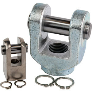
Double clevis
(5)
Exclusive body (-XB10)
Description
Part no.
Description
Stroke range
Example
Stroke range
1 to 29
1 to 49
1 to 99
Bore size
12, 16
20, 25
32 to 100
Stroke range
6 to 29
6 to 49
6 to 99
11 to 99
Bore size
12, 16
20, 25
32, 40
50 to 100
Manufacture of Intermediate Stroke
Type
Bore size (mm)
PneumaticAir-hydro
Mounting
Piping
Mounting
Piping
Through-hole (Standard)
Both ends tapped style
Through-hole (Standard)
Both ends tapped style
Built-in magnet
Built-in magnet
Rod end male thread
With rubber bumper
With boss in head side
Rod end male thread
With boss in head side
Screw-in type
Screw-in type
Built-in One-touch fittings
12
앬
앬
앬
—
앬
앬
앬
—
—
—
—
—
—
16
앬
앬
앬
—
앬
앬
앬
—
—
—
—
—
—
20
앬
앬
앬
—
앬
앬
앬
앬
앬
앬
앬
앬
25
앬
앬
앬
—
앬
앬
앬
앬
앬
앬
앬
앬
32
앬
앬
앬
ø6/4
(2)
앬
앬
앬
앬
앬
앬
앬
앬
40
앬
앬
앬
ø6/4
앬
앬
앬
앬
앬
앬
앬
앬
50
앬
앬
앬
ø8/6
앬
앬
앬
앬
앬
앬
앬
앬
63
앬
앬
앬
ø8/6
앬
앬
앬
앬
앬
앬
앬
앬
80
앬
앬
앬
—
앬
앬
앬
앬
앬
앬
앬
앬
100
앬
앬
앬
—
앬
앬
앬
앬
앬
앬
앬
앬
M5 x
0.8
M5 x
0.8
M5 x
0.8
M5 x
0.8
M5 x
0.8
M5 x
0.8
(1)
M5 x 0.8
Rc 1/8
(1)
M5 x 0.8
Rc 1/8
Rc
1/8
Rc
1/8
Rc
1/4
Rc
1/4
Rc
1/4
Rc
1/4
Rc
3/8
Rc
3/8
Rc
3/8
Rc
3/8
Fluid
Proof pressure
Maximum operating pressure
Ambient and
fluid temperature
Rubber bumper
Rod end thread
Rod end thread tolerance
Stroke length tolerance
Mounting
Piston speed
Specifications
Type Pneumatic (Non-lube)
Air
None
50 to 500 mm/s
Air-hydro
Turbine oil
5 to 50 mm/s
1.5 MPa
1.0 MPa
Female thread
JIS class 2
Through-hole
Air-hydro
5 to 60°C
(3)
+1.0
0
Note 3) For caution on handling, refer to page 7-13-6.
∗ For applications involving lateral loads, refer to anti-lateral load type on page 7-13-132.
Pneumatic (Non-lube)
Air-hydro
Minimum Operating Pressure
(MPa)
Bore size (mm)
12
0.07
—
16 20 25
0.18
32 40
0.05
50 63
0.10
80 100
Note 1) In the case of without auto switch, M5 x 0.8 is used for 5 stroke only.
Note 2) In the case of built-in fitting, the 5 mm stroke with ø32 bore is the same external dimensions as
10 mm stroke.
Spacer is installed in the standard
stroke body.
Dealing with intermediate stroke by the
1 mm interval is available by using
spacer with standard stroke cylinder.
Refer to “How to Order” for the standard
model no. on page 7-6-2.
Part No.: CQ2B50-57D
18 mm width spacer is installed in
the standard CQ2B50-75D.
B dimension is 115.5 mm.
Part no. CQ2B50-57D-XB10
Makes 57 stroke tube.
B dimension is 97.5 mm.
Dealing with the stroke by the 1 mm
interval by using an exclusive body
with the specified stroke.
Suffix “-XB10” to the end of standard
model no. on page 7-6-2.
When stroke exceeds the standard range, refer to
page 7-6-121.
Note 4) When ordering foot bracket, order 2
pieces per cylinder.
Note 5) Parts belonging to each bracket are as
follows. Foot, Flange: Body mounting
bolt/Double clevis: Clevis pin, Type C
snap ring for axis, body mounting bolt
• Air-hydro type is excluded.
• In the case of spacer type, intermediate stroke with damper for ø40 to ø100, it can be manufactured by 5 mm
intervals in 5 mm and 55 to 95 mm.
• In the case of an exclusive body with ø32 to ø100 (-XB10) with the stroke length exceeding 50 mm, the
reference values of the longitudinal dimension will be changed. Calculate length dimensions by deducting from
those of 75 or 100 mm stroke models.
• Regarding the long stroke which exceeds the stroke range, refer to page 7-6-121 for the long stroke type of
either CQ2 or CQS.
JIS Symbol
Double acting,
Single rod
JIS Symbol
With boss in
head side
Without auto switch:
–
10 to 70°C (No freezing)
With auto switch:
–
10 to 60°C (No freezing)
