MGC쏔쏔20
20
MGC쏔쏔25
25
M5 x 0.8 1/8
MGC쏔쏔32
32
MGC쏔쏔40
40
MGC쏔쏔50
50
Double acting
Air
1.5 MPa
1.0 MPa
0.15 MPa (Horizontal with no load)
–10 to 60°C
50 to 750 mm/s
Air cushion
Non-lube
+1.9
mm
∗ 1 When the cylinder is retracted (initial value), the non-rotating accuracy without loads or deflection of
the guide rods will be below the values shown in the table above as a guideline.
∗ 2 Bore sizes 20 and 25: M5 x 0.8 only
CDG1BA
20
25
32
40
50
8
10
12
16
20
0UT
IN
0UT
IN
0UT
IN
0UT
IN
0UT
IN
314
264
491
412
804
691
1260
1060
1960
1650
0.2
62.8
52.8
98.2
82.4
161
138
252
212
392
330
0.3
94.2
79.2
147
124
241
207
378
318
588
495
0.4
126
106
196
165
322
276
504
424
784
660
0.5
157
132
246
206
402
346
630
530
980
825
0.6
188
158
295
247
482
415
756
636
1180
990
0.7
220
185
344
288
563
484
882
742
1370
1160
0.8
251
211
393
330
643
553
1010
848
1570
1320
0.9
283
238
442
371
724
622
1130
954
1760
1490
1.0
314
264
491
412
804
691
1260
1060
1960
1650
(N)
OUT IN
250, 300, 350, 400
350, 400, 450, 500
350, 400, 450, 500, 600
350, 400, 450, 500, 600,
700, 800
350, 400, 450, 500, 600,
700, 800, 900, 1000
MGCM
(Slide bearing)
MGCL
(Ball bushing bearing)
75, 100, 125, 150, 200
75, 100, 125, 150,
200, 250, 300
20
25
32
40
50
-XB6
-XB13
-XC4
-XC6쏔
-XC8
-XC9
-XC11
-XC13
-XC22
-XC35
-XC37
-XC56
-XC73
-XC74
-XC78
-XC79
-X440
JIS Symbol
Specifications
Standard Stroke
Model (Bearing type)
Bore size
(mm)
Standard stroke (mm)
Long stroke (mm)
∗ Intermediate strokes and short strokes other than the above are produced upon receipt of order.
Specifications
Action
Fluid
Proof pressure
Maximum operating pressure
Minimum operating pressure
Ambient and fluid temperature
Piston speed
Cushion
Base cylinder lubrication
Stroke length tolerance
Non-rotating
accuracy
Piping port size (Rc, NPT, G)
Model
Base cylinder
Bore size (mm)
Slide bearing
Ball bushing bearing
Auto switch
Bore size
Port thread type
Stroke
+1.9
+0.2
±0.07°
±0.06°
±0.06°
±0.05°
±0.06°
±0.04°
±0.05°
±0.04°
±0.04°
±0.04°
1/4
Theoretical Output
Bore size
(mm)
Rod size
(mm)
Operating
direction
Piston area
(mm
2
)
Operating pressure (MPa)
Note) Theoretical output (N) = Pressure (MPa) x Piston area (mm
2
)
Note 1)
Note 2)
Made to Order Specifications
(For details, refer to pages 1829 to 1954, 1998.)
Symbol Specifications
Heat resistant cylinder (–10 to 150°C)
Low speed cylinder (5 to 50 mm/s)
With heavy duty scraper
Made of stainless steel
Adjustable stroke cylinder/Adjustable extension type
Adjustable stroke cylinder/Adjustable retraction type
Dual stroke cylinder/Single rod type
Auto switch rail mounting style
Fluororubber seals
With coil scraper
Larger throttle diameter of connecting port
With knock pin holes
Cylinder with lock (CDNG)
With front plate for MGG
Auto switch mounting special dimensions at stroke end
Machining tapped hole, drilled hole, and pin hole additionally
With piping ports for grease
393
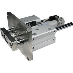
Guide Cylinder/Compact Type
Series MGC