How to Order
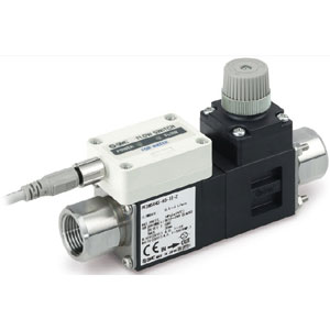
Digital Flow Switch for Water
Series PF3W
PF3W 7 04 03 AT M
Type
Remote sensor unit
Integrated display
5
7
Integrated
display
PF3W 5 04 03 1T
Remote
sensor unit
Thread type
Nil
N
F
Rc
NPT
G
0.5 to 4 L/min
2 to 16 L/min
5 to 40 L/min
10 to 100 L/min
50 to 250 L/min
04
20
40
11
21
Rated flow range (Flow range)
Symbol
Rated flow range
Bracket (Option)
None
Bracket
Nil
R
Made to Order
Note) Applicable only for remote type with
temperature sensor (Refer to page 10.)
Note) With bracket is not available for 250
L/min type.
Seal material EPDM
Analog 4 to 20 mA 2 output type
Note)
Piping material brass
X109
X128
X143
Output specification/Temperature sensor
Symbol
OUT1
Flow rate
Flow rate Temperature
—
—
—
—
—
—
—
—
NPN
PNP
Analog 1 to 5 V
Analog 4 to 20 mA
Analog 1 to 5 V
Analog 4 to 20 mA
A
B
C
D
E
F
G
H
AT
BT
CT
DT
ET
FT
NPN
PNP
Analog 1 to 5 V
Analog 4 to 20 mA
Analog 1 to 5 V
Analog 4 to 20 mA
External input
Note 1)
External input
Note 1)
(NPN)
(PNP)
(Analog 1 to 5 V)
(Analog 4 to 20 mA)
(Analog 1 to 5 V)
(Analog 4 to 20 mA)
NPN
PNP
NPN
NPN
PNP
PNP
NPN
PNP
NPN
PNP
NPN
NPN
PNP
PNP
3-color display
Port size
Symbol
Port
size
Rated flow range
03
04
06
10
12
14
04
$
—
—
—
—
—
20
$
$
—
—
—
—
40
—
$
$
—
—
—
11
—
—
$
$
—
—
21
—
—
—
—
$
$
3/8
1/2
3/4
1/1
1 1/4
1 1/2
Calibration certificate (Only flow sensor)
None
With calibration certificate
Nil
A
The certificate is written in both English and
Japanese. Integrated display type with
temperature sensor can only display flow rate.
Options/Part No.
When optional parts are required separately, use the following part numbers to place an order.
Part no. Qty.
1
1
1
1
Note
Description
ZS-40-K
ZS-40-L
ZS-40-M
ZS-40-A
For PF3W704/720/504/520
For PF3W740/540
For PF3W711/511
Bracket
Note)
Lead wire with M8 connector
Note 1) External input: The
accumulated value, peak
value, and bottom value
can be reset.
Note 2) For units with
temperature sensor,
OUT2 can be set as
either temperature output
or flow rate output.
Setting when shipped is
for temperature output.
Note) For units with flow adjustment valve, 2 brackets are required.
With 4 tapping screws (3 x 8)
With 4 tapping screws (3 x 8)
With 4 tapping screws (4 x 10)
Lead wire length (3 m)
Integrated display/Unit specification
Symbol
Temperature
oC
oC
oF
oF
Instantaneous flow rate
L/min
gal/min
gal/min
L/min
M
G
F
J
Accumulated flow
L
gal
gal
L
Remote sensor unit/Unit printed on label
Symbol
Temperature
oC
oC/oF
Instantaneous flow rate
L/min
L/min
(gal/min)
Nil
G
Under the New Measurement Law, units other
than SI (symbol “Nil”) cannot be used in Japan.
Note) G: Made to Order
Reference: 1 [L/min] 0.2642 [gal/min]
1 [gal/min] 3.785 [L/min]
oF = 9/5oC + 32
To use in combination with remote monitor (PF3W3 series),
select analog output of 1 to 5 V of flow rate (output symbol
“-1” or “-1T”).
Note) Analog output of 4 to 20 mA with temperature sensor is
made to order. (Refer to page 10.)
Under the New Measurement Law, units other
than SI (symbol “M”) cannot be used in Japan.
Note) G, F, J: Made to Order
Reference: 1 [L/min] 0.2642 [gal/min]
1 [gal/min] 3.785 [L/min]
oF = 9/5oC + 32
OUT2
Temperature
sensor
None
With
temperature
sensor
Note 2)
Note 2)
Note 2)
Note 2)
Note 2)
Note 2)
Integrated display
Output specification/Temperature sensor
Symbol
OUT1
Flow rate
OUT2
Temperature
Temperature
sensor
1
2
1T
—
—
Analog 1 to 5 V
None
With temperature sensor
Analog 1 to 5 V
Analog 4 to 20 mA
Analog 1 to 5 V
Remote sensor unit
ISO228 equivalent
None
Yes
Nil
S
Flow adjustment valve
Symbol
Rated flow range
With/without flow
adjustment valve
04
$
$
20
$
$
40
$
$
11
$
—
21
$
—
Note 1) 100 and 250 L/min types with flow adjustment
valves are not available.
Note 2)
The flow adjustment
valve of this product is
not suitable for
applications which
require constant
adjustment of flow rate.
For how to order of
remote monitor unit,
refer to page 18.
Lead wire
With lead wire with M8
connector
(3 m)
Nil
N
Without lead wire
with M8
connector
®
RoHS
1