Specifications
Bore size (mm)
Action
Fluid
Proof pressure
Max. operating pressure
Min. operating pressure
Ambient and fluid temperature
Lubrication
Operating piston speed
Allowable stroke tolerance
Cushion
Note 1)
Port size (Rc, NPT, G)
Mounting
32 40 63 100 12550 80
1/8 1/4 3/8 1/2
50 to
700 mm/s
Double acting, Single rod
Air
1.5 MPa
1.0 MPa
0.05 MPa
Without auto switch: –10 to 70°C (No freezing)
With auto switch: –10 to 60°C (No freezing)
Not required (Non-lube)
up to 250: , 251 to 1000: ,1001 to 1500:
Both ends (Air cushion)
Basic, Foot, Rod side flange, Head side flange,
Single clevis, Double clevis, Center trunnion
+1.0
0
+1.4
0
+1.8
0
50 to 1000 mm/s
Note 1) When requesting a cylinder without air cushion, cylinder utilizes rubber bumpers which
increases cylinders overall length.
JIS Symbol
Double acting
291
Standard Stroke
32
40
50
63
80
100
125
Bore
(mm)
25, 50, 75, 100, 125, 150, 175, 200, 250, 300, 350, 400, 450, 500
25, 50, 75, 100, 125, 150, 175, 200, 250, 300, 350, 400, 450, 500
25, 50, 75, 100, 125, 150, 175, 200, 250, 300, 350, 400, 450, 500, 600
25, 50, 75, 100, 125, 150, 175, 200, 250, 300, 350, 400, 450, 500, 600
25, 50, 75, 100, 125, 150, 175, 200, 250, 300, 350, 400, 450, 500, 600, 700, 800
25, 50, 75, 100, 125, 150, 175, 200, 250, 300, 350, 400, 450, 500, 600, 700, 800
25, 50, 75, 100, 125, 150, 175, 200, 250, 300, 350, 400, 450, 500, 600, 700, 800,1000
Standard stroke (mm)
Max.
stroke
700
800
1000
1000
1000
1000
1400
Intermediate strokes are available. (No spacer is used.)
Accessory
Mounting
Standard
Option
Rod end nut
Clevis pin
Single knuckle joint
Double knuckle joint
(with pin)
Rod boot
Basic Foot
Rod side
flange
Head side
flange
Single
clevis
Double
clevis
Center
trunnion
— — — — — —
Material of Rod Boot
Symbol
J
K
Material
Nylon tarpaulin
Heat resistant tarpaulin
Max. ambient temp.
70°C
110°C
∗
∗ Max. ambient temperature for rod boot itself.
Mounting Bracket Part No.
Note 1) Two foot brackets required for one cylinder.
Note 2) Accessories for each mounting bracket are as follows:
Foot, flange, single clevis/body mounting bolt, double clevis/body mounting bolt, clevis pins,
flat washer and cotter pins. → Refer to page 298 for details.
Foot
Note 1)
Flange
Single clevis
Double clevis
Bore size
(mm)
32
MB-L03
MB-F03
MB-C03
MB-D03
40
MB-L04
MB-F04
MB-C04
MB-D04
50
MB-L05
MB-F05
MB-C05
MB-D05
63
MB-L06
MB-F06
MB-C06
MB-D06
80
MB-L08
MB-F08
MB-C08
MB-D08
100
MB-L10
MB-F10
MB-C10
MB-D10
125
MB-L12
MB-F12
MB-C12
MB-D12
-XA쏔
-XB5
-XB6
-XB13
-XC3
-XC4
-XC5
-XC6
-XC7
-XC8
-XC9
-XC10
-XC11
-XC12
-XC14
-XC22
-XC27
-XC29
-XC30
-XC35
-XC59
-XC65
-X1184
Change of rod end shape
Oversized rod cylinder
Heat resistant cylinder (150°C)
Low speed cylinder (5 to 50 mm/s)
Special port position
With heavy duty scraper
Heat resistant cylinder (110°C)
Piston rod and rod end nut made of stainless steel
Tie rod, cushion valve, tie rod nut, etc.
made of stainless steel
Adjustable stroke cylinder/Adjustable extend stroke
Adjustable stroke cylinder/Adjustable retract stroke
Dual stroke cylinder/Double rod
Dual stroke cylinder/Single rod
Tandem cylinder
Change of trunnion bracket mounting position
Fluororubber seals
Double clevis pin and double knuckle
pin made of stainless steel
Double knuckle joint with spring pin
Rod side trunnion
With coil scraper
Fluororubber seal, Built-in hard plastic magnet
XC6 + XC7 specifications
Cylinder with reed, heat-resistant switch
Symbol Specifications
Made to Order Specifications
(For details, refer to pages 1373
to 1498 and 1515.)
Refer to pages 322 and 327 for cylinders
with auto switches.
• Minimum stroke for auto switch mounting
• Proper auto switch mounting position
(detection at stroke end) and mounting
height
• Operating range
• Switch mounting bracket: Part no.
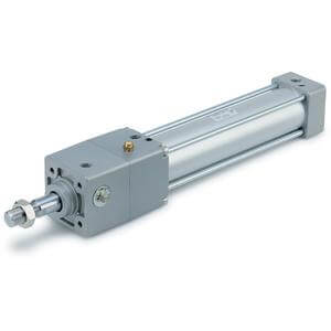
Air Cylinder: Single Rod
Series MB