RSQ
RSDQ
With auto switch
Without
auto switch
B
B
Built-in magnet
D
D
20
J79W20
15
15
Bore size
Mounting style
B
A
Through-hole (Standard)
Both ends tapped style
10
10, 15
10, 15, 20
10, 15, 20
20, 25, 30
Double acting
Double acting with spring loaded
Single acting (Spring extend)
Piping
Cylinder stroke (mm)
12
16
20
32
40, 50
Action
D
B
T
Auto switch
Note 3) The lever types are applicable only to bore sizes ø32,
ø40 and ø50.
Rod end configuration
Symbol
Nil
K
R
L
B
C
D
E
Configuration
Rounde bar type
Chamfered type
Roller type
Lever type (Non-adjustable)
(3)
Lever type
(3)
Energy absorbing
Adjustable deformation
Application
—
—
—
Basic style
—
With cancel cap
With lock menchanism
With lock & cancel
Number of
auto swiches
Applicable Auto Switch/Refer to page 10-20-1 for further information on auto switches.
12
16
20
32
40
50
12 mm
16 mm
20 mm
32 mm
40 mm
50 mm
Nil
F
Screw-in piping
Built-in One-touch fittings
(2)
Nil
Without auto switch
Nil
S
2 pcs.
1 pc.
Note 1) Since ø12 uses a common
tube for both A and B, only B
is used for part no. denotation.
Note 2) Bore sizes available w/ One-
touch fittings are ø20 to ø50.
Special functionType
Electrical
entry
Grommet
Grommet
Grommet
Grommet
Indicator light
Wiring
(Output)
2-wire
3-wire
(NPN equivalent)
Load voltage
—
AC
DC
Direct mounting
A96V
—
—
A93V
—
—
M9NV
M9PV
M9BV
—
F9NWV
F9PWV
F9BWV
—
—
—
Lead wire length (m)
∗
0.5
(Nil)
3
(L)
5
(Z)
앬
앬
앬
앬
앬
앬
앬
앬
앬
앬
앬
앬
앬
—
—
앬
앬
앬
앬
앬
앬
앬
앬
앬
앬
앬
앬
앬
앬
앬
앬
앬
—
—
앬
—
앬
—
앪
앪
앪
앬
앪
앪
앪
앪
앪
앪
IC circuit
Relay,
PLC
Applicable
load
• Since there are other applicable auto switches than listed, refer to page 10-8-14 for details.
• For details about auto switches with pre-wire connector, refer to page 10-20-66.
Rail mounting
Perpendicular
A96
—
—
A93
—
—
M9N
M9P
M9B
—
F9NW
F9PW
F9BW
F9BA
—
—
In-line
—
A72
A73
—
A73C
A79W
F7NV
F7PV
F7BV
J79C
F7NWV
—
F7BWV
—
F7BAV
—
Perpendicular
A76H
A72H
A73H
—
—
—
F79
F7P
J79
—
F79W
F7PW
J79W
F7BA
—
F79F
In-line
—
5 V
200 V—
100 V12 V
—
—
12 V
5 V, 12 V
12 V
5 V, 12 V
12 V
5 V, 12 V
—
—
—
—
24 V
Connector
Connector
Diagnostic indication
(2-color indication)
With diagnostic output
(2-color indication)
Water resistant
(2-color indication)
Diagnostic indication
(2-color indication)
—
—
2-wire
3-wire (NPN)
3-wire (NPN)
3-wire (PNP)
2-wire
3-wire (PNP)
4-wire (NPN)
24 V
IC circuit
—
IC circuit
—
IC circuit
Relay,
PLC
ø12, ø32 to ø50
ø16 to ø50
Reed switch
Solid state switch
Yes Yes
None
(N)
Pre-wire
connector
—
—
—
—
앬
—
—
—
—
앬
—
—
—
—
—
—
—
—
—
—
—
—
앪
앪
앪
—
앪
앪
앪
앪
—
앪
∗
Solid state switches marked with “앪” are produced upon receipt of order.
—
∗ For the applicable auto switch
model, refer to the table below.
∗ Auto switches are shipped
together, (but not assembled).
∗
Lead wire length symbols: 0.5 m··········Nil (Example) A73C
3 m·········· L (Example) A73CZ
5 m·········· Z (Example) A73CL
None·········· Z (Example) A73CN
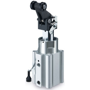
How to Order
Stopper Cylinder: Fixed Mounting Height
Series RSQ
ø12, ø16, ø20, ø32, ø40, ø50
10-8-3
RE
A
B
REC
C쏔X
C쏔Y
MQ
Q
M
RHC
MK(2)
RS
Q
G
RS
H
A
RZQ
MI
W
S
CEP1
CE1
CE2
ML2B
C
J
G
5-S
CV
MVGQ
CC
RB
J
D-
-X
20-
Data
3