Made to Order
(For details, refer to pages 211 to 231.)
Symbol Description
Applicable shaft type
-XA1 to -XA24
Shaft pattern sequencing!
S, W, Y
-XA33 to -XA59
Shaft pattern sequencing@
X, Z, T, J, K
-XC7
Reversed shaft
S, W, X, T, J
-XC8 to -XC11
Change of rotation range
S, W, Y
-XC30
Changed to fluorine
grease
S, W, X, Y,
Z, T, J, K
-XC31 to -XC36
Change of rotation range
and shaft rotation direction
S, W, Y
-XC59 to -XC61
Change of port direction
S, W, X, Y,
Z, T, J, K
-XC63, -XC64
One side air-hydro,
One side air
S, W, X, Y,
Z, T, J, K
-X6
Stainless steel shaft/
bolt, etc.
S, W, X, Y,
Z, T, J, K
-X7
*
Heat resistant (100°C)
S, W, X, Y,
Z, T, J, K
-X16
Fluororubber seal
S, W, X, Y,
Z, T, J, K
* -X7: Not available for the built-in magnet type
The shaft rotates clockwise when the pressure is
applied from the A port while it rotates counterclockwise
when the pressure is applied from the B port.
Specifications
Type Pneumatic Air-hydro
Size
30 50 63 80 100 50 63 80 100
Fluid Air (Non-lube) Turbine oil
Max. operating pressure
1.0 MPa
Min. operating pressure
0.1 MPa
Ambient and fluid
temperature
0 to 60°C (No freezing)
Cushion Not attached, Air cushion None
Backlash None
*
Within 1°
Tolerance in rotating angle
— 0 to +4°
* Since the CRA1l30 has a stopper installed, there is no backlash produced under pressure.
Effective Torque
[N·m]
Size
Operating pressure [MPa]
0.1 0.2 0.3 0.4 0.5 0.6 0.7 0.8 0.9 1.0
30
0.38 0.76 1.14 1.53 1.91 2.29 2.67 3.05 3.44 3.82
50
1.85 3.71 5.57 7.43 9.27 11.2 13.0 14.9 16.7 18.5
63
3.44 6.88 10.4 13.8 17.2 20.6 24.0 27.5 31.0 34.4
80
6.34 12.7 19.0 25.3 31.7 38.0 44.4 50.7 57.0 63.4
100
14.9 29.7 44.6 59.4 74.3 89.1 104 119 133 149
Allowable Kinetic Energy/Adjustable Range of Rotation Time Safe in Operation
Size
Allowable kinetic energy [J]
Adjustable range of rotation
time safe in operation [s/90°]
Without air cushion
With air cushion
*
30
0.01 0.12
Cushion angle
35°
0.2 to 1
50
0.05 0.98 0.2 to 2
63
0.12 1.50 0.2 to 3
80
0.16 2.00 0.2 to 4
100
0.54 2.90 0.2 to 5
* Allowable kinetic energy of the product with air cushion is the maximum absorbed energy when
the cushion valve adjustment is optimized.
Weight
Size
Standard weight Additional weight
90° 180°
With auto switch
*
Foot bracket Flange bracket
30
0.27 0.36 0.1 0.1 —
50
1.3 1.5 0.2 0.3 0.5
63
2.2 2.6 0.4 0.5 0.9
80
3.9 4.4 0.6 0.9 1.5
100
7.3 8.3 0.9 1.2 2.0
* With 2 auto switches
[kg]
Foot Bracket/Part No.
Size Foot bracket Contents
Mounting screw size
included in foot bracket
30
CRA1L 30-Y-1Z
Foot bracket : 2 pcs.
Mounting screw : 4 pcs.
Collar
*
: 4 pcs.
M 5 x 0.8 x 25
50
CRA1L 50-Y-1Z M 8 x 1.25 x 35
63
CRA1L 63-Y-1Z M10 x 1.5 x 40
80
CRA1L 80-Y-1Z M12 x 1.75 x 50
100
CRA1L100-Y-1Z M12 x 1.75 x 50
*Size 30 does not include collars.
* Remove the basic type mounting screws and use the mounting screws included in the foot
bracket to secure the foot bracket to the cover. Use the collar as a spacer for the cover
counterbore part and secure it together with the foot.
* For size 30, be careful not to drop the cover when removing the basic type mounting screws.
Additionally, do not mount the foot bracket with the pressure applied to the port.
Flange type
Basic type
Foot type
Symbol
Rotation Range of Keyway
Size: 50 to 100
Size: 30
189
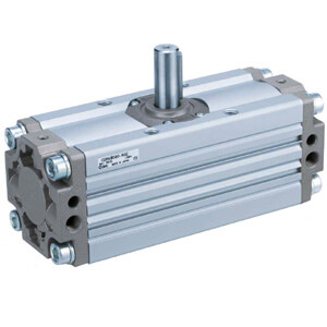
Rotary Actuator
Rack & Pinion Type
CRA1 Series