AS FR
M9BW
Adjuster option
Functional option
Without adjuster
Adjuster on extension end
Adjuster on retraction end
Adjuster on both ends
Absorber on extension end
Absorber on retraction end
Absorber on both ends
Adjuster on extension end
+ Absorber on retraction end
Absorber on extension end + Adjuster on retraction end
Standard
With buffer
With end lock
Axial piping type
With buffer and end lock
With buffer, Axial piping type
Nil
F
R
(2)
P
FR
(2)
FP
Nil
AS
AT
A
BS
BT
B
ASBT
BSAT
Adjuster
option
Functional
option Nil F R P FR FP
Option Combinations
Auto switch
Nil
Without auto switch (Built-in magnet)
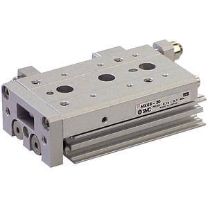
Air slide table
Nil
AS
AT
A
BS
(1)
BT
(1)
B
(1)
ASBT
(1)
BSAT
(1)
MXS 12 50
∗ Lead wire length symbols: 0.5 m ·········· Nil (Example) M9NW
1 m ·········· M (Example) M9NWM
3 m ·········· L (Example) M9NWL
5 m ·········· Z (Example) M9NWZ
∗ Solid state auto switches marked with “ ” are produced upon receipt of order.
∗ Since there are additional applicable auto switches than are listed, refer to page 82 for details.
∗ For details on auto switches with a pre-wired connector, refer to pages 1784 and 1785.
∗ Auto switches are shipped together (not assembled).
Applicable Auto Switches/Refer to pages 1719 to 1827 for further information on auto switches.
Made to order
For details refer
to page 55.
Note 1) Options BS, BT and B are not available with the
MXS6 series.
: Available : Not available
A96V
A93V
A90V
M9NV
M9PV
M9BV
M9NWV
M9PWV
M9BWV
A96
A93
A90
M9N
M9P
M9B
M9NW
M9PW
M9BW
Type Special function
—
24 V
Grommet
24 V
3-wire (NPN)
3-wire (PNP)
2-wire
3-wire (NPN)
3-wire (PNP)
2-wire
3-wire
(NPN equivalent)
2-wire
Ye s
No
Ye s
Electrical
entry
Load voltage
Wiring
(Output)
Pre-wired
connector
Applicable load
DC AC
Auto switch model
Lead wire length (m)
Perpendicular
In-line
0.5
(Nil)
5
(Z)
Grommet
—
100 V
100 V or less
—
1
(M)
IC
circuit
—
IC
circuit
—
IC
circuit
—
IC circuit
—
Relay,
PLC
Relay,
PLC
—
—
Diagnostic indication
(2-color indication)
5 V, 12 V
12 V
5 V, 12 V
12 V
5 V
12 V
3
(L)
Port thread type
Nii
TN
TF
M thread
Rc
NPT
G
ø6 to ø16
ø20, ø25
10, 20, 30, 40, 50
10, 20, 30, 40, 50, 75
10, 20, 30, 40, 50, 75, 100
10, 20, 30, 40, 50, 75, 100, 125
10, 20, 30, 40, 50, 75, 100, 125, 150
10, 20, 30, 40, 50, 75, 100, 125, 150
6
8
12
16
20
25
Bore size (Stroke (mm))
2 pcs.
1 pc.
“n” pcs.
Nil
S
n
Number of auto switches
∗ For the applicable auto switch models, refer to the
table below. For the applicable auto switches for
buffer, refer to page 73.
Note 2) Option R is not available
with the MXS6 series.
Note 3) When the buffer mechanism and the stroke adjuster on
extension end are combined, the buffer stroke will be
shorter by the length adjusted by the stroke adjuster on the
extension end.
Indicator
light
Reed
switch
Solid state
switch
54
Air Slide Table
Series MXS
How to Order
(3)
(3)
(3)
(3) (3)