RoHS
How to Order
ø6, ø8, ø12, ø16, ø20, ø25
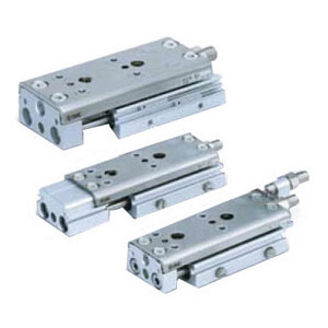
MXQA Series
Air Slide Table
Double-ported Type
q
Bore
size
Body option:
w
Double-ported type
e
Standard stroke [mm]
A
6
10, 20, 30, 40, 50
8
10, 20, 30, 40, 50, 75
12
10, 20, 30, 40, 50, 75, 100
16
10, 20, 30, 40, 50, 75, 100, 125
20
10, 20, 30, 40, 50, 75, 100, 125, 150
25
10, 20, 30, 40, 50, 75, 100, 125, 150
∗
30 ZAMXQ 12
M9BW
A
∗ For applicable auto switches,
refer to the next page.
Symbol Functional option
Nil
Without functional option
1
With buffer
2
With end lock
3
Axial piping
4
With buffer, end lock
5
With buffer, axial piping
6
Centralized adjuster
7
Centralized adjuster (Symmetric)
8
Buffer, Centralized adjuster
9
Buffer, Centralized adjuster (Symmetric)
Nil
Without auto switch
Nil
2
S
1
n
n
Symbol Adjuster type
∗
9
Adjuster mounting
position
∗
1
∗
8
Functional option combination
Nil 1 2 3 4 5 6 7 8 9
Extension
stroke end
Retraction
stroke end
Without
functional
option
∗
2
∗
3
With
buffer
With
end lock
∗
6
Axial
piping
∗
2
With buffer,
end lock
∗
2
∗
6
With Buffer,
axial piping
Centralized
adjuster
∗
7
Centralized adjuster
(Symmetric)
∗
2
Buffer, Centralized
adjuster
∗
2
∗
7
Buffer, Centralized
adjuster (Symmetric)
Z
Without adjuster
× × × ×
ZA
Metal stopper with bumper
× ×
× ×
× ×
ZB
×
× × × × × ×
ZC
× ×
× ×
ZD
Rubber stopper
× ×
× ×
ZE
× × × ×
ZF
× ×
× ×
ZG
Shock absorber/RJ
× ×
× ×
× ×
ZH
×
× × × × × ×
ZJ
× ×
× ×
ZK
Metal stopper
× ×
× ×
ZL
× × × ×
ZM
× ×
× ×
ZN
Shorter total
length type
∗
4
Retraction stroke end adjuster
Without adjuster
∗
5
×
×
∗
5
× × × ×
ZP
Rubber stopper
× ×
× × × × × ×
ZQ
Shock absorber/RJ
× ×
× × × × × ×
ZS
Metal stopper with bumper
× ×
× × × × × ×
ZT
Metal stopper
× ×
× × × × × ×
ZBF
Extension stroke end adjuster
Metal
stopper with
bumper
Rubber stopper
× ×
× ×
× ×
ZBJ
Shock absorber/RJ
× ×
× ×
× ×
ZBM
Metal stopper
× ×
× ×
× ×
ZEC
Rubber
stopper
Metal stopper with bumper
× ×
× ×
ZEJ
Shock absorber/RJ
× ×
× ×
ZEM
Metal stopper
× ×
× ×
ZHC
Shock
absorber/RJ
Metal stopper with bumper
× ×
× ×
× ×
ZHF
Rubber stopper
× ×
× ×
× ×
ZHM
Metal stopper
× ×
× ×
× ×
ZLC
Metal
stopper
Metal stopper with bumper
× ×
× ×
ZLF
Rubber stopper
× ×
× ×
ZLJ
Shock absorber/RJ
× ×
× ×
r Adjuster options/Functional option combinations
y Auto switch
t Functional options u Number of
auto switches
q w e r t y u i
For details, refer to the
next page.
i Made to order
∗ Because piping ports and auto switch grooves are provided on both sides,
only the adjuster part of the centralized adjuster is symmetric.
∗ The operating speed range of the stroke marked with an asterisk (∗) is 50 to
300 mm/s. (Without stroke adjuster)
∗1 : Shipped together with the product, but not assembled
Without any symbol for the adjuster mounting position: The adjuster can be
mounted afterward.
∗2 For the buffer mechanism, the buffer stroke will be shorter for the stroke that
is adjusted by the extension stroke end adjuster.
∗3 If it is necessary to install a retraction stroke end adjuster with a buffer
mechanism, use a buffer and centralized adjuster provided with a retraction
stroke end adjuster on the rear end of the body. End lock or axial piping
options cannot be mounted to centralized adjuster specification models.
∗4 Extension stroke end adjuster mounting holes have been removed to reduce
the total length of the table.
∗5 The shorter total length type can be used, but a retraction stroke end adjuster
cannot be mounted afterward.
∗6 For axial piping, the piping ports on both sides cannot be used.
∗7 Only the centralized adjuster is symmetric.
∗8 For details on the adjuster mounting position, refer to the next page.
∗9 The metal stopper with bumper option is not available for ø6.
11