VIDEO:
30 SECOND
PART BUILDER
EXPLAINED
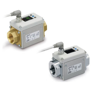
LFE is a digital flow sensor for water and non-corrosive conductive liquids. While the PF3W sensors detect flow using the Karman vortex principle, LFE applies Faraday's law of induction. There are no obstacles or moving parts in the flow path, yielding a smaller pressure loss which saves pumping energy. Detectable liquids have fewer viscosity restraints. Finally, the flow direction can be changed after installation. The 2-screen, 3-color display can show the measured value in the primary screen, while viewing a variey of secondary data in the sub-screen. Two outputs are available, including two switch signals, or a switch and analog signal. Options include a mounting bracket and M12 lead wire. Piping connections are C37 brass as standard, while the -X8 option offers 304 stainless steel. LFE is IP65 rated, and CE and RoHS compliant.
Part Number
Configure to get your Part Number
