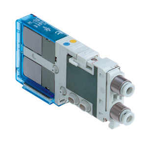
J: PC wiring (20 pins)
Note
Up to 16
solenoids
possible.
2 stations
16 stations
Symbol Stations
02
16
Symbol
D
Mounting position
D side
Connector mounting position
Connector entry
direction
1
: Upward
2
: Lateral
60 DF 1 U
Series
SJ2000/3000
SUP/EXH block fitting spec.
Nil
Straight fitting
L
Elbow fitting
(Upward)
B
Elbow fitting
(Downward)
Internal pilot
Internal pilot / Built-in silencer
External pilot
External pilot / Built-in silencer
Pilot spec.
Nil
S
R
RS
How to Order
SS5J 3
P Connector type manifold
Series
SJ2000
SJ3000 (SJ2000/3000 mixed)
2
3
05
Mixed mounting type
Nil
M
Note 1) There is no need to enter
anything when you operate
either the SJ2000 or
SJ3000 series alone.
Note 2) Enter “M” when the SJ2000
or SJ3000 series will be
mounted on the same
manifold base together.
Standard
Note 1)
Mixed mounting
Note 2)
With external pilot
spec.
X, PE port
With external pilot
spec.
X, PE port
With external pilot
spec.
X, PE port
F: D-sub connector
Valve stations
Note
Up to 24
solenoids
possible.
2 stations
24 stations
Symbol Stations
02
24
PG: Flat ribbon cable (20 pins)
Note
Up to 18
solenoids
possible.
2 stations
18 stations
Symbol Stations
02
18
P: Flat ribbon cable (26 pins)
Note
Up to 24
solenoids
possible.
2 stations
24 stations
Symbol Stations
02
24
PH: Flat ribbon cable (10 pins)
Note
Up to 8
solenoids
possible.
2 stations
8 stations
Symbol Stations
02
08
∗ The number of the blanking block as-
sembly is also included. Since single
and double wiring are available with the
blanking block assembly, select a mod-
el compatible with the valve wiring
spec. planned for the future. (Refer to
page 61.)
∗ Specify the required
specifications (includ-
ing port sizes other
than ø8) by means of
the manifold specifi-
cation sheet.
SUP/EXH block mounting position
U
D
B
M
∗
U side (2 to 10 stations)
D side (2 to 10 stations)
Both sides (2 to 24 stations)
Special specifications
How to Order Valve Manifold Assembly
• The valve arrangement is numbered as the 1st station from D side.
• Indicate the valves to be attached below the manifold part number, in order starting from
station 1 as shown in the drawing.
In the case of complex arrangement, specify them in the
manifold specification sheet.
The asterisk denotes the symbol for assembly.
Prefix to the part no. of the solenoid valve, etc.
Ordering example (SS5J3-60PD2-l)
SS5J3-60PD2-06D 1 set (Manifold part no.)
∗ SJ3160-5CU-C6 2 sets (Single solenoid part no.)
∗ SJ3260-5CU-C6 2 sets (Double solenoid part no.)
∗ SJ3260-5CZJ-C6 1 set (Double solenoid, with switch part no.)
∗ SJ3260-5MZ-C6
1 set (Double solenoid, individual wiring/lead wire length 300 mm part no.)
D
side
U side
13
2
Stations
SJ3260-5MZ-C6 (1 set)
SJ3260-5CZJ-C6 (1 set)
Double solenoid, with switch (24 VDC)
Double solenoid, individual wiring/lead wire length 300 mm (24 VDC)
SJ3260-5CU-C6 (2 sets)
Double solenoid (24 VDC)
SJ3160-5CU-C6 (2 sets)
Single solenoid (24 VDC)
SUP/EXH block (D side mounting)
D-sub Connector / Flat Ribbon Cable /
PC Wiring
Plug-in
Connector Type
F
:
D-sub connector
(25 pins)
P
:
Flat ribbon cable
(26 pins)
PG
:
Flat ribbon cable
(20 pins)
PH
:
Flat ribbon cable
(10 pins)
J
: PC wiring
(20 pins)
Connector type
PCW type
DIN rail length specified
Specify a longer
rail than the
standard length.
Standard length
3 stations
24 stations
Nil
3
24
∗ Specify the valve stations not exceeding
the maximum stations.
∗ Refer to page 26 through to 33 for PCW type with power supply
terminal.
∗ There is no need to enter anything when the
SUP/EXH block mounting position “M” is selected.
∗ There is no need to enter anything when the SUP/EXH block
mounting position “M” is selected.
∗ For built-in silencers, the 3/5(E) ports are plugged.
10
