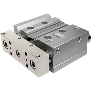
Symbol
Rubber bumper
Standard Strokes
Manufacture of Intermediate Strokes
Theoretical Output
Specifications
Bore size
[mm]
Rod size
[mm]
Operating
direction
Piston area
[mm
2
]
Operating pressure [MPa]
0.2 0.3 0.4 0.5 0.6 0.7 0.8 0.9 1.0
12
6
OUT 113 23 34 45 57 68 79 90 102 113
IN 85 17 25 34 42 51 59 68 76 85
16
8
OUT 201 40 60 80 101 121 141 161 181 201
IN 151 30 45 60 75 90 106 121 136 151
20
10
OUT 314 63 94 126 157 188 220 251 283 314
IN 236 47 71 94 118 141 165 188 212 236
25
10
OUT 491 98 147 196 245 295 344 393 442 491
IN 412 82 124 165 206 247 289 330 371 412
32
14
OUT 804 161 241 322 402 483 563 643 724 804
IN 650 130 195 260 325 390 455 520 585 650
40
14
OUT 1257 251 377 503 628 754 880 1005 1131 1257
IN 1103 221 331 441 551 662 772 882 992 1103
50
18
OUT 1963 393 589 785 982 1178 1374 1571 1767 1963
IN 1709 342 513 684 855 1025 1196 1367 1538 1709
63
18
OUT 3117 623 935 1247 1559 1870 2182 2494 2806 3117
IN 2863 573 859 1145 1431 1718 2004 2290 2576 2863
80
22
OUT 5027 1005 1508 2011 2513 3016 3519 4021 4524 5027
IN 4646 929 1394 1859 2323 2788 3252 3717 4182 4646
100
26
OUT 7854 1571 2356 3142 3927 4712 5498 6283 7069 7854
IN 7323 1465 2197 2929 3662 4394 5126 5858 6591 7323
*1: Maximum speed with no load. Depending on the operating conditions, the piston speed may
not be satisfied.
Make a model selection, considering a load according to the graph on pages 439 to 445.
*: Theoretical output [N] = Pressure [MPa] x Piston area [mm
2
]
[N]
Description
Spacer installation type
Spacers are installed in the standard stroke cylinder.
•
ø12 to ø32
: Available in 1 mm stroke increments.
•
ø40 to ø100
: Available in 5 mm stroke increments.
Exclusive body (-XB10)
Dealing with the stroke by making an exclusive body.
•
All bore sizes are available in 1 mm increments.
Model no.
Refer to How to Order for the standard model numbers.
Add “-XB10” to the end of standard model number. For details, refer to Made to Order.
Applicable
stroke [mm]
ø12, ø16 1 to 249 ø12, ø16 11 to 249
ø20, ø25, ø32 1 to 399 ø20, ø25 21 to 399
ø40 to ø100 5 to 395 ø32 to ø100 26 to 399
Example
Part no.: MGPM20-39Z
A spacer 1 mm in width is installed in the
MGPM20-40. C dimension is 77 mm.
Part no.: MGPM20-39Z-XB10
Special body manufactured for 39 stroke.
C dimension is 76 mm.
*1: The shape is the same as the current product.
Made to Order
(For details, refer to pages 1247 to 1440.)
Symbol Specifications
-XA
Change of guide rod end shape
-XB6
Heat resistant cylinder (−10 to 150°C)
-XB10
Intermediate stroke (Using exclusive body)
-XB13
Low speed cylinder (5 to 50 mm/s)
-XB22
Shock absorber soft type
RJ series type
-XC4
With heavy duty scraper
-XC6
Made of stainless steel
-XC8
Adjustable stroke cylinder/Adjustable extension type
-XC9
Adjustable stroke cylinder/Adjustable retraction type
-XC22
Fluororubber seal
-XC35
With coil scraper
-XC69
With shock absorber
*
1
-XC79
Tapped hole, drilled hole, pinned hole machined additionally
-XC82
Bottom mounting type
-XC85
Grease for food processing equipment
-XC88
Spatter resistant coil scraper, Lube-retainer, Grease
for welding (Rod parts: Stainless steel 304)
-XC89W
Spatter resistant coil scraper, Lube-retainer,
Grease for welding (Rod parts: S45C)
-XC91
Spatter resistant coil scraper, Grease for
welding (Rod parts: S45C)
-XC92
Dust resistant actuator
*
1
Refer to pages 486 to 490 for cylinders
with auto switches.
• Auto switch proper mounting position
(detection at stroke end) and its mounting
height
• Minimum stroke for auto switch mounting
• Operating range
• Auto switch mounting brackets/Part no.
• Auto Switch Mounting
Bore size [mm] Standard stroke [mm]
12, 16
10, 20, 30, 40, 50, 75, 100, 125, 150, 175, 200, 250
20, 25
20, 30, 40, 50, 75, 100, 125, 150, 175, 200, 250, 300, 350, 400
32 to 100
25, 50, 75, 100, 125, 150, 175, 200, 250, 300, 350, 400
Bore size [mm]
12 16 20 25 32 40 50 63 80 100
Action
Double acting
Fluid
Air
Proof pressure
1.5 MPa
Maximum operating pressure
1.0 MPa
Minimum operating pressure
0.12 MPa 0.1 MPa
Ambient and fluid temperature
−10 to 60°C (No freezing)
Piston speed
*
1
50 to 500 mm/s
50 to 400 mm/s
Cushion
Rubber bumper on both ends
Lubrication
Not required (Non-lube)
Stroke length tolerance
+1.5
0
mm
Made to Order: Individual Specifications
(For details, refer to page 491.)
Symbol Specifications
-X144
Symmetrical port position
-X867
Side porting type (Plug location changed)
433
Compact Guide Cylinder
MGP Series
