Clamping height
LOW type
KQGC X2081
X2082
KQGC
Clamping height
HIGH type
Bore size
Guide pin shape
Number of auto switches
With lock
Guide pin diameter
Mounting surface position
(viewed from top)
BL 32 075 R A L C
BL 32 075 R A H C
Clamp arm position (clockwise viewed from top)
Auto switch type
∗Auto switches are shipped together, (but not
assembled).
∗
Refer to the table below for the applicable auto switches.
∗When the total thickness of clamped
workpiece is over 2 mm, the auto switch may
not be adjusted to the most sensitive position.
∗
Secure the minimum bending radius of the auto
switch lead wire before use (Refer to page 544).
Table 1. Guide Pin Diameter
Applicable Auto Switches/Refer to pages 941 to 1067 for further information on auto switches.
Note 1) PLC: Programmable Logic Controller
Note 2) There are applicable auto switches other than the listed above. For details, refer to page 545.
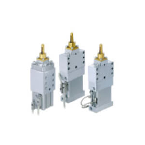
Compact Cylinder Type
∗For guide pin diameter,
refer to Table 1 below.
Pin Clamp Cylinder
C(L)KQG32 Series
Symbol
Clamp arm position
Symbol
Clamp arm position
A
Same as the port side
C
180° from the port side
B
90° from the port side
D
270° from the port side
Nil
Without auto switch (Built-in magnet)
C
D-P3DWASC
E
D-P3DWASE
N
D-P3DWA
L
D-P3DWAL
Z
D-P3DWAZ
Symbol
Mounting surface position
A
B
C
D
Nil
Without lock
L
With lock
Nil
2 pcs.
S
1 pc. (Unclamping side)
R
Round type
D
Diamond type
32
32 mm
Symbol
115 116 117 118 119 120 125 126 127 128 129 130 135 136 137 138 139 140 145 146 147 148 149 150
Guide pin diameter [mm] 11.5 11.6 11.7 11.8 11.9 12.0 12.5 12.6 12.7 12.8 12.9 13.0 13.5 13.6 13.7 13.8 13.9 14.0 14.5 14.6 14.7 14.8 14.9 15.0
Applicable hole diameter of workpiece [mm]
For ø12 For ø13 For ø14 For ø15
Guide pin shape Round type/Diamond type
Symbol
155 156 157 158 159 160 175 176 177 178 179 180 195 196 197 198 199 200
Guide pin diameter [mm] 15.5 15.6 15.7 15.8 15.9 16.0 17.5 17.6 17.7 17.8 17.9 18.0 19.5 19.6 19.7 19.8 19.9 20.0
Applicable hole diameter of workpiece [mm]
For ø16 For ø18 For ø20
Guide pin shape Round type/Diamond type
Type Auto switch model
Applicable
magnetic field
Electrical entry
Indicator
light
Wiring
(Pin no. in use)
Load
voltage
Lead wire
length
Applicable
load
Solid state
auto switch
D-P3DWASC
AC magnetic field
(Single-phase AC
welding magnetic field)
Pre-wired connector
2-color
indicator
2-wire (3–4)
24 VDC
0.3 m
Relay,
PLC
Note 1)
D-P3DWASE
2-wire (1–4)
D-P3DWA
Grommet 2-wire
0.5 m
D-P3DWAL
3 m
D-P3DWAZ
5 m
Symbol
075 076 077 078 079 080 085 086 087 088 089 090 095 096 097 098 099 100 105 106 107 108 109 110
Guide pin diameter [mm]
7.5 7.6 7.7 7.8 7.9 8.0 8.5 8.6 8.7 8.8 8.9 9.0 9.5 9.6 9.7 9.8 9.9
10.0 10.5 10.6 10.7 10.8 10.9 11.0
Applicable hole diameter of workpiece [mm]
For ø8 For ø9 For ø10 For ø11
Guide pin shape Round type Round type/Diamond type
ø32
529