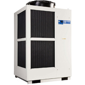
Thermo-chiller
Air-cooled 200 V Type
Inverter Type
HRSH Series
How to Order
A 20
HRSH
Specifications
Model
HRSH100-Al-20-l HRSH150-Al-20-l HRSH200-Al-20-l HRSH250-Al-20-l HRSH300-Al-20-l
Cooling method Air-cooled refrigeration
Refrigerant R410A (HFC)
Refrigerant charge
kg 1.27 2.1 2.1 2.8 2.8
Control method PID control
Ambient temperature/Altitude
Note 1), 9)
°C Temperature: –20 to 45, Altitude: less than 3000 m
Circulating fluid system
Circulating fluid
Note 1), 2)
Tap water, 15 to 40% Ethylene glycol aqueous solution, Deionized water
Set temperature range
Note 1)
°C 5 to 35
Cooling capacity
Note 3), 9)
kW 10.5 15.7 20.5 25 28
Heating capacity
Note 4)
kW 2.5 3 5.5 7.5
Temperature stability
Note 5)
°C
±0.1
Pump
capacity
Rated flow (Outlet)
L/min 45 (0.43 MPa) 45 (0.45 MPa) 125 (0.5 MPa)
Maximum flow rate L/min 120 130 180
Maximum pump head
m 50 80
Settable pressure range
Note 6)
MPa 0.1 to 0.5 0.1 to 0.8
Minimum operating flow rate
Note 7)
L/min 20 25 40
Tank capacity L 25 42 60
Circulating fluid outlet, circulating fluid return port
Rc1 (Symbol F: G1, Symbol N: NPT1)
Tank drain port Rc3/4 (Symbol F: G3/4, Symbol N: NPT3/4)
Automatic
fluid fill
system
(Standard)
Supply side pressure range
MPa 0.2 to 0.5
Supply side fluid temperature
°C 5 to 35
Automatic fluid fill port Rc1/2 (Symbol F: G1/2, Symbol N: NPT1/2)
Overflow port
Rc1 (Symbol F: G1, Symbol N: NPT1)
Fluid contact material
Metal Stainless steel, Copper (Heat exchanger brazing), Brass, Bronze
Resin PTFE, PU, FKM, EPDM, PVC, NBR, POM, PE, NR
Electrical system
Power supply
3-phase 200 VAC (50 Hz), 3-phase 200 to 230 VAC (60 Hz)
Allowable voltage range ±10% (No continuous voltage fluctuation)
Applicable earth
Note 8)
leakage breaker
Rated current
A 30 40 50
Sensitivity of leak current
mA 30
Rated operating current
Note 5)
A 14 17 25 34 36
Rated power consumption
Note 5)
kW (kVA)
4.5 (4.9) 5.8 (6) 8.4 (8.7) 10.4 (11.6) 11.1 (12.2)
Noise level (Front 1 m/Height 1 m)
Note 5)
dB (A) 68 71
Waterproof specification IPX4
Accessories
Alarm code list stickers 2 pcs. (English 1 pc./Japanese 1 pc.),
Operation Manual (for installation/operation) 2 pcs. (English 1 pc./Japanese 1 pc.),
Y-strainer (40 meshes) 25A, Barrel nipple 25A, Anchor bolt fixing brackets 2 pcs. (including 6 M8 bolts)
Note 10)
Weight (dry state) kg Approx. 180 Approx. 215 Approx. 280
Note 1)
When the ambient temperature or circulating fluid temperature is 10°C or below, refer to "Operation at low ambient temperature or low circulating fluid temperature" (page 186-1).
Note 2) Use fluid in condition below as the circulating fluid.
Tap water: Standard of The Japan Refrigeration And Air Conditioning Industry Association (JRA GL-02-1994)
15 to 40% ethylene glycol aqueous solution: Diluted with clean water, without any additives such as antiseptics. (Refer to "Operation at low ambient temperature or low cir-
culating fluid temperature" (page 186-1) for the concentration of the ethylene glycol aqueous solution.)
Deionized water: Electric conductivity 1 μS/cm or higher (Electric resistivity 1 MΩ·cm or lower)
Note 3) q Ambient temperature: 32°C, w Circulating fluid: Tap water, e Circulating fluid temperature: 20°C, r Circulating fluid flow rate: Rated flow, t Power supply: 200 VAC
Note 4) q Ambient temperature: 32°C, w Circulating fluid: Tap water, e Circulating fluid flow rate: Rated flow, r Power supply: 200 VAC
Note 5) q Ambient temperature: 32°C, w Circulating fluid: Tap water, e Circulating fluid temperature: 20°C, r Load: Same as the cooling capacity, t Circulating fluid flow rate:
Rated flow, y Power supply: 200 VAC, u Piping length: Shortest
Note 6) With the pressure control mode by inverter. When the pressure control mode is not used, the pump power frequency set mode can be used.
Note 7) Fluid flow rate to maintain the cooling capacity and the temperature stability. If the actual flow rate is lower than this, install a bypass piping.
Note 8)
To be prepared by user. A specified earth leakage breaker is installed for option B [With earth leakage breaker], B1 [With earth leakage breaker with handle] and S [Conforming to CE/UL standards].
Note 9) If the product is used at altitude of 1000 m or higher, refer to “Operating Environment/Storage Environment” (page 186) Item 13 “* For altitude of 1000 m or higher”.
Note 10) The anchor bolt fixing brackets (including 6 M8 bolts) are used for fixing to wooden skids when packaging the thermo-chiller. No anchor bolt is included.
Option
Nil
None
A
With caster adjuster-foot
B
With earth leakage breaker
B1
With earth leakage breaker with handle
K
Note 1)
With fluid fill port
S
Note 2)
Conforming to CE/UL standards
When multiple options are combined, indicate symbols in alphabetical order.
Note 1) This is a manual fluid fill port that is different from the automatic fluid fill port.
Fluid can be supplied manually into the tank without removing the side panel.
(Fluid can be supplied manually for models without option K if the side panel
is removed.)
Note 2) Combination with option B or option B1 is not necessary. The earth leakage
breaker with a handle (Option B1) is provided as standard.
Power supply
20
3-phase 200 VAC (50 Hz)
3-phase 200 to 230 VAC (60 Hz)
Pipe thread type
Nil
Rc
F
G
(with Rc-G conversion fitting)
N
NPT (with Rc-NPT conversion fitting)
Cooling method
A
Air-cooled refrigeration
Cooling capacity
100
10.5 kW
150
15.7 kW
200
20.5 kW
250
25 kW
300
28 kW
250
RoHS