Action
Fluid
Proof pressure
Maximum operating pressure
Minimum operating pressure
Ambient and fluid temperature
Cushion
Lubrication
Thread tolerance
Stroke length tolerance
Piston speed
Allowable kinetic energy
ø10
ø16
1 to 300 mm/s
0.035 J
0.090 J
Specifications
Double acting, Single rod
Air
1.05 MPa
0.7 MPa
0.06 MPa
+1.0
0
Bore size (mm)
10
16
Standard stroke (mm)
15, 30, 45, 60, 75, 100, 125, 150
15, 30, 45, 60, 75, 100, 125, 150, 175, 200
Standard Stroke
Mounting Style and Accessory
Port Location on Head Cover
Mounting Bracket Part No.
Auto Switch Mounting Bracket Part No.
(Band mounting style)
Precautions
1. During installation, secure the rod cover and
tighten by applying an appropriate tightening
force to the retaining but or to the rod cover
body.
If the head cover is secured or the head cover
is tightened, the cover could rotate, leading to
the deviation.
2. Proper tightening torque for mounting thread
should be within the range specified. Apply a
Loctite
®
(no. 242 Blue) for mounting thread.
3. To remove and install the snap ring for the
knuckle pin or the clevis pin, use an
appropriate pair of pliers (tool for installing a
type C snap ring).
Especially with ø10, use ultra thin pliers, such
as Super Tool Corp., CSM-07A.
4. For the auto switch mounting rail, do not
remove the pre-equipped rail. Since the
mounting thread is drilled through inside a the
cylinder, it will result in air leakage.
Mounting
Caution
1. It might not be able to control by meter-out at
a low speed operation.
Operating Precautions
Warning
1. For Series CJ2X, 0.1 Nl/min is the values at
maximum in terms of its construction and
there is internal leakage (ANR).
Caution
∗ Pin and snap ring are shipped together with double clevis and double knuckle joint.
Mounting
Standard
equipment
Option
Mounting nut
Rod end nut
Clevis pin
Single knuckle joint
Double knuckle joint
∗
T-bracket
앬
앬
앬
앬
앬
앬
앬
앬
앬
앬
앬
앬
앬
앬
앬
앬
앬
Basic
style
Axial foot
style
Rod side
flange style
Double
∗
clevis style
Mounting
bracket
Foot bracket
Flange bracket
T-bracket
∗
Bore size (mm)
10
CJ-L010B
CJ-F010B
CJ-T010B
16
CJ-L016B
CJ-F016B
CJ-T016B
∗ T-bracket is used with double clevis (D).
Common for the types of
D-C7/C8 and D-H7
Bore size
(mm)
10
16
Auto switch mounting
bracket part no.
BJ2-010
BJ2-016
Note
Axial direction Perpendicular
Bore size
(mm)
Proper tightening torque for mounting thread
(N·m) (tightening torque for mounting nut)
10
16
3.0 to 3.2
5.4 to 5.9
Without auto switch: –10 to 70°C (No freezing)
With auto switch: –10 to 60°C (No freezing)
Rubber bumper (Standard equipment)
Not required (Non-lube)
JIS Class 2
JIS Symbol
Double acting,
Single rod
Be sure to read before handling. For Safety
Instructions and Actuator Precautions,
refer to pages 10-24-3 to 10-24-6.
For basic style, the port position in a head cover is available either perpendicular to the axis
or in-line with the cylinder axis.
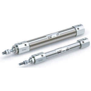
Series CJ2X
10-3-7
Low Speed Cylinder
Double Acting, Single Rod
RE
A
B
REC
C쏔X
C쏔Y
MQ
Q
M
RHC
MK(2)
RS
Q
G
RS
H
A
RZQ
MI
W
S
CEP1
CE1
CE2
ML2B
C
J
G
5-S
CV
MVGQ
CC
RB
J
D-
-X
20-
Data