(EA) 5 1
(P)
3 (EB)
2 (B)(A) 4
(EA) 5 1
(P)
3 (EB)
2 (B)(A) 4
(EA) 5 1
(P)
3 (EB)
2 (B)(A) 4
(EA) 5 1
(P)
3 (EB)
2 (B)(A) 4
(A) 4 2 (B)
1
(P)
(EA) 5 3 (EB)
5(EA) 3(EB)1(P)
2(B)4(A)
5(EA) 3(EB)1(P)
2(B)4(A)
5(EA) 3(EB)1(P)
4(A) 2(B)
5 1 LL 3
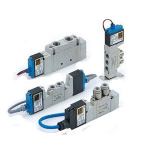
Intrinsically Safe Valve
5 Port Solenoid Valve
Single Unit
Body Ported
How to Order
SY53 20
01
UL/CSA
compliant
5
7
9
53-SY5000
53-SY7000
53-SY9000
Series
1
2-position single
Type of actuation
2
2-position double
3
Note 1)
3-position closed center
4
Note 1)
3-position exhaust center
5
Note 1)
A
Note 2)
B
Note 2)
C
Note 2)
3-position pressure center
Note 1) 3-position type is not available for the
53-SY9000 series.
Note 2) 4-position dual 3 port valves are
available for 53-SY5000 only.
Nil
F
N
T
Rc
G
NPT
NPTF
Thread type
∗ Bracket is not available for
the 53-SY9000.
Nil: Without bracket
F1: With foot bracket
2-position
single only
F2: With side bracket
Bracket
Manual override
Symbol Port size
Applicable series
53-SY5000
53-SY7000
53-SY9000
1/8
1/4
1/4
3/8
Thread piping
A, B port size
01
02
02
03
Symbol
Port size
ø4 One-touch fitting
ø6 One-touch fitting
ø8 One-touch fitting
ø8 One-touch fitting
ø10 One-touch fitting
ø8 One-touch fitting
ø10 One-touch fitting
ø12 One-touch fitting
Applicable series
53-SY5000
53-SY7000
53-SY9000
One-touch fitting (Metric size)
Note)
C4
C6
C8
C8
C10
C8
C10
C12
Symbol
Port size
ø5/32" One-touch fitting
ø1/4" One-touch fitting
ø5/16" One-touch fitting
ø5/16" One-touch fitting
ø3/8" One-touch fitting
ø5/16" One-touch fitting
ø3/8" One-touch fitting
Applicable series
53-SY5000
53-SY7000
53-SY9000
One-touch fitting (Inch size)
Note)
N3
N7
N9
N9
N11
N9
N11
Symbol
3
6
10
15
20
30
100
Lead wire length
300 mm
600 mm
1000 mm
1500 mm
2000 mm
3000 mm
10000 mm
Note
—
Maximum length for L-type
—
—
—
—
Semi-standard
Lead wire length
Symbol
L
Electrical entry
L-type plug connector
Electrical entry
Note) The lead wire of TT-type is connected to the
terminal block.Use only supplied cable and nut.
LL
L-type plug connector
with cover
TT
Note)
Terminal type
Note)
If a resin tubing is used,
take precautions against
static electricity.
Warning
Series 53-SY5000/7000/9000
The solenoid must be connected to a safety
barrier located in a non-hazardous area.
The safety barrier must meet the specifica-
tions listed in the Installation Instructions
section.
Warning
Electrical Entry TT
Hazardous Location
Class I, II, III
Division 1
Groups A, B, C, D, E, F, G
Do not install in Zone 0 (as defined in IEC 60079-10-1: 2008) or Zone 20
(as defined in IEC 60079-10-2: 2009)(Refer to page 40 for details)
Electrical Entry L and LL
Hazardous Location
Class I
Division 1
Groups A, B, C, D
Warning
4-position dual 3 port valves (N.C./N.O.)
4-position dual 3 port valves (N.O./N.O.)
4-position dual 3 port valves (N.C./N.C.)
Nut
Nil: Non-locking push
type
D: Push-turn locking
slotted type
E: Push-turn locking
lever type
2