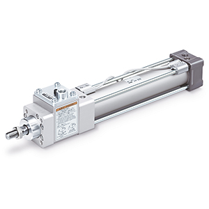
Cylinder with Lock
Double Acting, Single Rod
MWB Series
Lock Unit Specifications
∗1
The holding force (max. static load) shows the maximum capability and does not show the normal
holding capability. Be sure to select a cylinder using the method described in Model Selection (page 5).
Bore size [mm]
32 40 50 63 80 100
Locking action Exhaust locking
Max. operating pressure
1.0 MPa
Min. operating pressure
0.08 MPa
Locking direction Both directions
Holding force (Max. static load) [N]
∗
1
630 980 1570 2450 3920 6080
For details of cylinders with auto switches
e pages 24 to 30
·
Auto Switch Proper Mounting Position (Detection
at stroke end) and Mounting Height
· Minimum Stroke for Auto Switch Mounting
· Auto Switch Mounting Brackets/Part Nos.
· Operating Range
Ordering Example of
Cylinder Assembly
Cylinder model: MDWBD32-50-NW-M9BW
∗
Pivot bracket, double knuckle joint, and auto switch are
shipped together with the product, but not assembled.
Mounting D: Double clevis
Pivot bracket N: Yes
Rod end bracket W: Double knuckle joint
Auto switch D-M9BW: 2 pcs.
Cylinder Specifications
∗1
Load limits exist depending upon the piston speed when locked, mounting direction, and operating pressure.
Bore size [mm]
32 40 50 63 80 100
Action Double acting, Single rod
Fluid Air
Proof pressure 1.5 MPa
Max. operating pressure
1.0 MPa
Min. operating pressure
0.08 MPa
Ambient and fluid
temperatures
Without auto switch: −10°C to 70°C
With auto switch: −10°C to 60°C
(No freezing)
Lubricant Not required (Non-lube)
Piston speed 50 to 1000 mm/s
∗
1
Stroke length tolerance
Up to 250 st:
+1.0
0
, 251 to 1000 st:
+1.4
0
, 1001 to 1500 st:
+1.8
0
, 1501 to 2000 st:
+2.2
0
Cushion Air cushion or Rubber bumper
Port size (Rc, NPT, G) 1/8 1/4 3/8 1/2
Mounting
Basic, Axial foot, Rod flange, Head flange
Single clevis, Double clevis, Center trunnion
Pivot bracket
Standard Strokes
∗ When using with auto switches, refer to the Minimum Stroke for
Auto Switch Mounting table on pages 26 to 28.
Bore
size
Standard stroke
Max.
manufacturable
stroke
Stroke range q
Stroke range
w
32
25, 50, 75, 100, 125, 150, 175, 200, 250, 300, 350, 400, 450, 500
Up to 1000
Up to 2500
40
25, 50, 75, 100, 125, 150, 175, 200, 250, 300, 350, 400, 450, 500
Up to 1800
50
25, 50, 75, 100, 125, 150, 175, 200, 250, 300, 350, 400, 450, 500, 600
63
25, 50, 75, 100, 125, 150, 175, 200, 250, 300, 350, 400, 450, 500, 600
80
25, 50, 75, 100, 125, 150, 175, 200, 250, 300, 350, 400, 450, 500, 600, 700, 800
100
25, 50, 75, 100, 125, 150, 175, 200, 250, 300, 350, 400, 450, 500, 600, 700, 800
∗ The manufacturing of intermediate strokes is possible. (Spacers are not used.)
∗
Applicable strokes should be confirmed according to the usage. For details, refer to the Air Cylinders
Model Selection in the Web Catalog or Best Pneumatics Catalog. In addition, products that exceed
the stroke range q might not be able to fulfill the specifications due to deflection, etc.
∗ Please consult with SMC for details on manufacturability and for part numbers when exceeding
the stroke range w.
∗ When using a rod boot, a stroke range of up to 1000 mm is available. Please consult with SMC
when exceeding a 1000 mm stroke.
[mm]
Stopping Accuracy
Bore size [mm]
32 40 50 63 80 100
Lock type Exhaust locking
Stopping accuracy [mm]
±1.0
Conditions
· Mounting orientation: Horizontal
· Supply pressure: 0.5 MPa
· Piston speed: 300 mm/s
· Load condition: Upper limit of allowed value
Solenoid valve for locking is mounted on the unlock port.
Maximum value of stopping position dispersion from 100 measurements
Symbol Specifications
-XAm
Change of rod end shape
-XC35
With coil scraper
Symbol Specifications
-X3000
Dimensionally compatible with the MNB series
Made to Order Common Specifications
(For details, refer to pages 36 to 38.)
Made to Order Individual Specifications
(For details, refer to page 35.)
8
MWBMWBWMWB-UT
Model Selection
Double Acting, Single RodDouble Acting, Double RodLock Unit
Made to Order Auto Switch