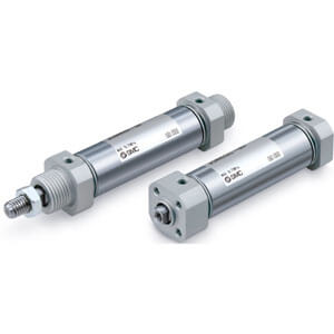
Double acting, Single rod
Symbol
Bore size [mm]
20 25 32 40
Type Pneumatic
Action Double acting, Single rod
Fluid Air
Proof pressure 1.0 MPa
Maximum operating pressure 0.7 MPa
∗
2
Minimum operating pressure 0.05 MPa
Ambient and fluid temperature 5 to 60°C (No freezing)
Lubrication Not required (Non-lube)
Stroke length tolerance
+2.0
0
mm
Piston speed
∗
1
50 to 500 mm/s
∗
2
Cushion Rubber bumper
Allowable kinetic
energy [J]
Male thread 0.11 0.18 0.29 0.52
Female thread
0.11 0.18 0.18 0.52
Refer to pages 11 to 13 for cylinders with
auto switches.
· Auto Switch Proper Mounting Position
(Detection at stroke end) and Mounting
Height
· Minimum Stroke for Auto Switch Mounting
· Method of Mounting Two Auto Switches at
the Stroke End of a Cylinder for Strokes
Less Than 20 mm
· Precautions for Mounting Two D-M9 In-line
Entry Type Auto Switches on the Same
Surface
· Operating Range
· Auto Switch Mounting Brackets/Part No.
∗ Refer to page 10 for dimensions.
∗1 Can be used for M and MZ only.
Mounting bracket
Minimum
order
quantity
Bore size [mm]
Contents
20 25 32 40
Mounting nut (M5, Rc1/8, NPT1/8)
∗
1
1 JSN-020B JSN-032B JSN-040B 1 mounting nut
Rod end nut 1 NT-02 NT-03 NT-04 1 rod end nut
Segment Description Material Surface treatment
Mounting
bracket
Mounting nut Carbon steel Zinc chromated
Rod end nut Carbon steel Zinc chromated
∗ Operate the cylinder within the allowable kinetic energy.
∗1 Depending on the system configuration selected, the specified speed may not be satisfied.
∗2
Maximum operating pressure and piston speed are different from the current product (CM2 series).
∗1 Intermediate strokes not listed above are produced upon receipt of order.
The minimum stroke is 25 mm.
Bore size
[mm]
Standard stroke [mm]
∗
1
20
25, 50, 75, 100, 125, 150, 200, 250, 300
25
32
40
Standard Strokes
Specifications
Mounting Brackets/Part No.
Mounting Brackets/Material, Surface Treatment
4
Air Cylinder
Double Acting, Single Rod
JCM Series