6
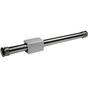
Series NCY3B
Air
152 PSI (1.05 MPa)
101 PSI (0.7MPa)
Refer to the minimum operating pressure table.
14 to 140°F (–10 to 60
C) (No freezing)
2 to 20 inch/s (50 to 500 mm/s)
Rubber bumper on both ends
Non-lube
Horizontal, Inclined, Vertical
Note)
Standard equipment (accessory)
Fluid
Proof pressure
Max. operating pressure
Min. operating pressure
Ambient and fluid temperature
Piston speed
Cushion
Lubrication
Mounting orientation
Mounting nut (2 pcs.)
Specifications
Theoretical Cylinder Thrust
Caution
Unit: oz
Basic weight
45.40 (oz)
Additional weight
0.59 (oz/inch)
Cylinder stroke
20 (inch)
45.40 + (0.59 x 20) = 57.20 (oz)
Weight
JIS symbol
Calculation method/Example: NCY3B32-2000
Basic weight (at 0 st)
Main Material
Description
Head cover
Cylinder tube
Body
Magnet
Material
Aluminum alloy
Stainless steel
Aluminum alloy
Rare earth magnet
Note
Electroless nickel plated
Hard anodized
Minimum Operating Pressure
XB6
XB9
XB13
X116
X132
X160
X168
X206
X210
X322
X324
X1468
XC24
XC57
Heat resistant specification
Low speed specification (0.6 to 2.0 inch/s)
Low speed specification (0.3 to 2.0 inch/s)
Air Hydro specification
Axial ports
High speed specification
Helical insert thread specification
Added mounting tap positions for slider
Oil-free exterior specification
Outside of cylinder tube with hard chrome plating
Oil-free exterior specification (with dust seal)
Interchangeable specification with NCY2B6
With magnetic shielding plate
With floating joint
Symbol Specifications
Made to Order
(Refer to pages 9 for details.)
When calculating the actual thr-ust, design should
consider the minimum actuating pressure.
Magnetically Coupled Rodless Cylinder
Basic Type
Bore
size
(mm)
(inch-nominal)
6
1/4"
1.83
0.07
10
3/8"
2.82
0.25
15
5/8"
9.70
0.27
20
3/4"
12.38
0.36
25
1"
23.70
0.41
32
1-1/4"
45.40
0.59
40
1-1/2"
73.02
0.72
50
2"
112.88
1.38
63
2-1/2"
186.95
1.72
Additional weight
per 1 inch stroke
Note) For details, refer to the construction drawings
on page 7.
Note) When vertically mounting, it is impossible to perform an intermediate stop by pneumatic circuit.
Note) Values show when the cylinder is driving
without load.
30
25
20
15
10
5
0
6
(1/4")
10
(3/8")
15
(5/8")
20
(3/4")
25
(1")
32
(1-1/2")
40
(1-1/2")
50
(2")
63
(2-1/2")
Bore size [mm (inch)]
Minimum operating pressure (PSI)
23 23 23 23
22
20
17 17 17
0 to 10 st (inch): 0 to 0.04 inch (1.0 mm)
10.01 to 40 st (inch): 0 to 0.06 inch (1.4 mm)
40.01 st (inch): 0 to 0.07 inch (1.8 mm)
Stroke length tolerance
Theoretical thrust (Ibf)
Supply pressure (PSI)
600
500
0255075
100
100
200
300
400
ø63 (2-1/2")
ø50 (2")
Theoretical thrust (Ibf)
Supply pressure (PSI)
14
12
0255075
100
2
4
6
8
10
ø10 (3/8")
ø6 (1/4")
Theoretical thrust (Ibf)
Supply pressure (PSI)
250
200
0255075
100
50
100
150
ø40 (1-1/2")
ø32 (1-1/4")
ø20 (3/4")
ø25 (1")
ø15 (5/8")
ø6, ø10 ø15, ø20, ø25, ø32, ø40
ø50, ø60
Made to
Order