Series
CKQ D/CLKQ D
G
P
G
P
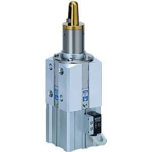
Pin Clamp Cylinder
D series
Clamp arm position (clockwise viewed from top)
A
B
C
D
Clamp arm
Guide pin
Same direction as port
90° from port
180° from port
270° from port
Clamp arm
Guide pin
Clamp arm
Guide pin
Port
Clamp arm
Guide pin
Port
Port
Port
Round type Diamond type
KQG
Built-in standard magnet
With magnetic field
resistant auto switch
KQP
C
C
Built-in strong magnet
With magnetic field
resistant auto switch
With lock on the clamp side
L
Nil
Without lock
With lock
Body shape
D
Dimen-
sion
Mounting
Mounting hole (tap, pin
hole) arrangement
Mounting
surface (viewed
from top)
Mounting surface
(Two facing sides)
Symbol
쏔66
Mounting tap:
4 x M10 x 1.5
Pin hole:
2 x ø8H7
50
50 mm
Bore size
Port thread type
TN
TF
Nil
Rc
NPT
G
R
D
Round type
Diamond type
∗
Guide pin shape
∗ Diamond type guide pin
diameter is ø17.5 or more.
Number of auto switches
S
Nil
2 pcs.
1 pc. (Unclamp side)
∗
The D-P4/P7 type is different-surface
mounting. (Refer to page 1308.)
Auto switch type
Nil
Without auto switch
(Built-in magnet)
∗ For applicable auto switch models,
refer to page 1269.
∗ Auto switches are included, (but
not assembled).
Shim
S
Nil
Without shims
With 3 mm shims
∗
∗ When a model includes shims, two 1 mm
shims and two 0.5 mm shims are
attached.
Clamping height
(Refer to the below figure.)
L
H
LOW type (60 mm)
HIGH type (90 mm)
Clamping height
LOW type HIGH type
Guide pin diameter
Table 1. Guide Pin Diameter
Guide pin diameter
Applicable hole diameter of workpiece
Guide pin shape
Round type
For ø15 For ø16For ø13
12.5
12.7 12.8 12.9 13.0 14.5 14.7 14.8 14.9 15.0 15.5 15.7 15.8 15.9 16.0
Symbol
125 127 128 129 130 145 147 148 149 150 155 157 158 159 160
Guide pin diameter
Applicable hole diameter of workpiece
Guide pin shape
Round type, Diamond type
For ø20 For ø25For ø18
17.5 17.7 17.8 17.9 18.0 19.5 19.7 19.8 19.9 20.0 24.5 24.7 24.8 24.9 25.0
Symbol
175 177 178 179 180 195 197 198 199 200 245 247 248 249 250
For ø30
29.5 29.7 29.8 29.9 30.0
295 297 298 299 300
Mounting surface (viewed from top)
A
B
Port locationSymbol
Port
Mounting surface
Port
∗ For guide pin diameter, refer to Table 1 below.
D A 50 177 R A L
P4DWSC
D A 50 198 R A L
P79WSE
60
90
: Mounting tap
: Pin hole
Mounting
surface
How to Order
1268