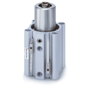
During unclamping
(Extension end)
80° to 100°
(90°±10°)
L type
(Counterclockwise)
During unclamping
(Extension end)
80° to 100°
(90°±10°)
R type
(Clockwise)
Clamp part
During clamping (Retraction end)
Non-rotating accuracy
±0.7° to 1.4°
Port side
MK Series
-X2071
-X2094
-X2172
-X2177
Max. operating pressure 1.0 MPa
Overall length is the same as the MK2 series
With boss in head end
Symbol Description
Made to Order: Individual Specifications
(For details, refer to pages 401 and 402.)
Note) Theoretical output (N) = Pressure (MPa) x Piston area (cm
2
) x 100
Operating direction IN: Clamp OUT: Unclamp
Bore size
(mm)
12
16
20
25
32
40
50
63
Rod size
(mm)
Operating
direction
6
8
12
12
16
16
20
20
IN
OUT
IN
OUT
IN
OUT
IN
OUT
IN
OUT
IN
OUT
IN
OUT
IN
OUT
Piston area
(cm
2
)
0.8
1.1
1.5
2.0
2.0
3.1
3.8
4.9
6.0
8.0
10.6
12.6
16.5
19.6
28.0
31.2
0.3
25
34
45
60
60
94
113
147
181
241
317
377
495
589
841
935
0.5
42
57
75
101
101
157
189
245
302
402
528
628
825
982
1402
1559
0.7
59
79
106
141
141
220
264
344
422
563
739
880
1155
1374
—
—
1.0
85
113
151
201
201
314
378
491
603
804
1056
1257
1649
1963
—
—
Operating pressure (MPa)
Unit: N
Note 1) Refer to Rotary Angle figure.
Note 2) Direction of rotation viewed from the rod end when the piston rod is retracting
Note 3) Clamp force at 0.5 MPa
Note 4) When using the cylinder within a pressure range from 0.61 to 1 MPa, please use –X2071.
Note 5) Be sure to install a speed controller to the cylinder, and adjust the cylinder speed to make it within the
range from 50 to 200 mm/s. To adjust the speed, start with the needle in the completely closed position,
and then adjust it by opening gradually.
Action
Rotary angle
Note 1)
Rotary direction
Note 2)
Rotary stroke (mm)
Clamp stroke (mm)
Theoretical clamp force (N)
Note 3)
Fluid
Proof pressure
Operating pressure range
Ambient and fluid temperature
Lubrication
Piping port size
Bore size (mm)
Double acting
90° ±10°
Clockwise, Counterclockwise
Air
1.5 MPa
0.1 to 1 MPa
Without auto switch: –10 to 70°C (No freezing)
With auto switch: –10 to 60°C (No freezing)
Non-lube
Rubber bumper
50 to 200 mm/s
12 16 20 25 32 40 50
7.5 9.5 15 19
10, 20, 30 10, 20, 30, 50
63
40 75 100 185 300
Through-hole/Both ends tapped common, Head flange
525 825
±1.4° ±1.2° ±0.9° ±0.7°
M5 x 0.8
1400
+0.6
–
0.4
0.1 to
0.6 MPa
Rc1/8, NPT1/8
G1/8
Rc1/4, NPT1/4
G1/4
Note 4)
Mounting
Cushion
Stroke length tolerance
Piston speed
Note 5)
Non-rotating accuracy (Clamp part)
Note 1)
Specifications
Rotary Angle
Theoretical Output
The dimension of head end flange is the
same as the current series MK and MK2.
Bore size (mm) Part no. Accessories
Clamp bolt,
Hexagon socket
head cap screw,
Hexagon nut,
Spring washer
Option/Arm
Bore size (mm) Rod flange Accessories
Special hexagon socket head cap screw
(4 pcs.)
Special hexagon socket head cap screw
(2 pcs.)
Special hexagon socket head cap screw
(4 pcs.)
Mounting Bracket/Flange
MK-A012Z
MK-A016Z
MK-A020Z
MK-A032Z
MK-A050Z
12
16
20
25
32
40
50
63
12
16
20
25
32
40
50
63
MKZ-RF012
MKZ-RF016
MKZ-RF020
MKZ-RF025
MKZ-RF032
MKZ-RF040
MKZ-RF050
MKZ-RF063
Head flange
CQS-F012
CQS-F016
MKZ-F020
MKZ-F025
MK2T-F032
MK2T-F040
MK2T-F050
MK2T-F063
-XB6
Heat resistant cylinder (-10 to 150°C)
w/o auto switch only
Note 1)
-XC22
Fluororubber seals
Note 2)
Symbol Description
Note 1) Except ø12 and ø16.
Note 2) The bumper is a standard product.
Made to Order Specifications
(For details, refer to pages 1069 to 1262.)
390
B
