10000
5000
3000
2000
1000
500
300
200
100
-30B
XT316
1 2 3 4 5 6 7 8 9 10 11 12
Hopper thickness T(mm)
4 Units
3 Units
2 Units
1 Unit
Hopper Diameter D(mm)
T: Hoppe
r th
icknes
s
D: Hopper diameter
XT316
-40B
XT316
-63B
XT316
-80B
XT316
-100B
Bridge
Adhesion
(Note 1) Change in potential energy applied to a pendulum
(Note 2) Total weight including the mounting base and bolts
Model
Bore size
Operating pressure MPa (kgf/cm
2
)
Impact cycle (cycles/min)
Air consumption ( /cycles)
(Note 1) Impact energy (kgm)
(Note 2) Weight (kg)
Ambient and fluid temperature
Port size (PT)
Lubrication
Specifications
XT316-30B
XT316-40B
XT316-63B
XT316-80B
XT316-100B
Ø30
0.33
0.05 - 0.07
2.5
Ø40
0.75
0.17 - 0.31
4.4
Ø63
0.4 - 0.6 (4.1 - 6.1)
MAX. 15
1.29
0.45 - 0.75
11.2
32 - 140 °F (0 - 60 °C)
1/8
Not lubricated
Ø80
1.91
1.0 - 1.8
15
Ø100
4
2.2 -4.0
33.5
3/8
Variable impact force
Strong, stable impact force
No lubrication required
How to Order
Model Selection
Suppose the diameter and thickness of the hopper are 500mm
and 4mm, respectively. According to the intersection of the lines
representing the diameter and thickness, one XT316-63B should
be selected.
The model of an air shocker to be selected depends on the type,
shape, and size of the machine on which the air shocker is mounted,
as well as the degree of adhesion and plugging. However, the
following diagram will provide a guideline on selection of the type and
number of air shockers.
Example)
XT316 – 40 B
Air shocker
Bore size
Base
30
40
63
80
100
Ø30
Ø40
Ø63
Ø80
Ø100
B
With base
Without base
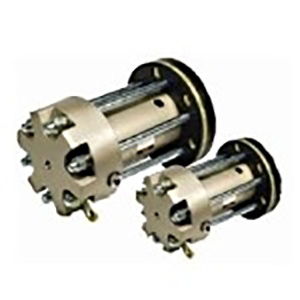
Air Shocker
Series XT316
Consult
factory
2