20, 25
32, 40, 50, 63, 80, 100
Bore size (mm)
5, 10, 15, 20, 25, 30, 35, 40, 45, 50
10, 15, 20, 25, 30, 35, 40, 45, 50, 75, 100
Standard stroke (mm)
Spacer is installed in the standard stroke body.
Refer to
“How to Order” for the standard model no. on page 816.
Part no.: CLQB40-47D-B
3 mm spacer is installed in standard cylinder CLQB40-50D-B.
B dimension is 79.5 mm.
Stroke range (mm)
1 to 50
1 to 100
Bore size (mm)
20, 25
32, 40, 50, 63, 80, 100
Description
Part no.
Method
Stroke range
Example
Extension locking Retraction locking
W
W
JIS Symbol
Bore size (mm)
Double acting, Single rod
Air
1.5 MPa
1.0 MPa
0.2 MPa
Note 1)
Without auto switch: –10 to 70°C (No freezing)
With auto switch: –10 to 60°C (No freezing)
Non-lube
50 to 500 mm/s
None, rubber bumper
20 25 32 40 50 63 80 100
M5 x 0.8 1/8 1/4 3/8
Bore size (mm)
Spring locking (Exhaust locking)
0.2 MPa or more
0.05 MPa or less
One direction (Either extension locking or retraction locking)
Equivalent to 0.5 MPa
20 25 32 40 50 63 80 100
157 245 402 629 982 1559 2513 3927
M5 x 0.8Rc
NPT
G
1/8
1/4
1/4
1/8M5 x 0.8
—XA쏔
—XC35
Change of rod end shape
With coil scraper (ø40 to ø100 only)
Symbol
Specifications
Refer to pages 834 to 837 for cylinders
with auto switches.
Made to Order Specifications
(For details, refer to pages 1836 and 1926.)
• Minimum auto switch mounting stroke
• Proper auto switch mounting position (detection
at stroke end) and mounting height
• Operating range
• Switch mounting bracket: Part no.
—
817
Standard Stroke
Cylinder Specifications
Lock Specifications
Manufacture of Intermediate Stroke
Action
Fluid
Proof pressure
Maximum operating pressure
Minimum operating pressure
Ambient and
fluid temperature
Lubrication
Piston speed
Stroke length tolerance
Cushion
Port size (Rc, NPT, G)
Locking action
Unlocking pressure
Lock starting pressure
Locking direction
Unlocking port size
Holding force (N)
(Maximum static load)
mm
Note 2)
+1.0
0
Dealing with the stroke by the 1 mm interval is available by
installing spacer with standard stroke cylinder.
Note 1) The minimum operating pressure of the cylinder is 0.1 MPa when the cylinder and lock
are connected to separate ports.
Note 2) Stroke length tolerance does not include the amount of bumper change.
Note) Be sure to select cylinders referring page 812.
Note) ø40 to ø100 bumper spacers with intermediate strokes can be manufactured in 5 mm
increments from 55 to 95 mm.
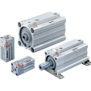
Series CLQ
Compact Cylinder with Lock
Double Acting, Single Rod