How to Order
PFM
7 10 C4 A M
1
2
S
IN
1
2
S
IN
1
1
2
S
IN
1
2
S
IN
1
1
2
S
IN
1
2
S
IN
1
2
S
IN
1
1
2
S
IN
1
®
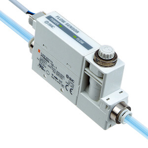
2-Color Display
Digital Flow Switch
Series PFM7
Integrated
display
Integrated
display
Unit specification
Note) Fixed unit: Real-time flow rate: l/min
Accumulated flow: l
Fixed SI unit
Note)
With unit switching function
M
Nil
Type
Integrated display
7
Flow adjustment valve
Nil
S
None
Yes
Calibration certificate
None
With calibration certificate
Nil
A
∗ The certificate is written in English and Japanese.
Other languages are available as specials.
Instruction manual
With instruction manual (Leaflet: Japanese and English)
None
Nil
N
Note 3) User can select from accumulated value
external reset, auto-shift and auto-shift zero.
Output specification
A
B
C
D
E
F
G
H
2 NPN outputs
2 PNP outputs
1 NPN output + Analog (1 to 5 V)
1 NPN output + Analog (4 to 20 mA)
1 PNP output + Analog (1 to 5 V)
1 PNP output + Analog (4 to 20 mA)
1 NPN output + External input
Note 3)
1 PNP output + External input
Note 3)
Piping entry direction
Nil
L
Straight
Bottom
Port size
Symbol Description
Flow rate range
10
쎲
쎲
쎲
쎲
쎲
25
쎲
쎲
쎲
쎲
쎲
쎲
50
쎲
쎲
쎲
쎲
쎲
쎲
11
쎲
쎲
쎲
쎲
쎲
쎲
01
02
N01
N02
F01
F02
C4
C6
C8
N7
ø4 (5/32") one-touch fitting
ø6 one-touch fitting
ø8 (5/16") one-touch fitting
ø1/4" one-touch fitting
Rc1/8
Rc1/4
NPT1/8
NPT1/4
G1/8
G1/4
0.2 to 10 (5) l/min
0.5 to 25 (12.5) l/min
1 to 50 (25) l/min
2 to 100 (50) l/min
10
25
50
11
∗ ( ): Fluid: CO2
Rated flow range (Flow rate range)
Option 1
(Refer to page 907.)
Option 2
(Refer to page 907.)
Made to Order
(Refer to page 907 and 940.)
∗ Different combinations of
piping entry directions for
IN and OUT side are
available as made-to-order.
(Refer to page 940.)
With one-touch fittings (C4, C6, C8, N7) Female thread (01, 02, N01, N02, F01, F02)
Straight (Nil)
Without
flow
adjustment
valve
(Nil)
With
flow
adjustment
valve
(S)
Bottom (L)
Straight (Nil) Bottom (L)
Piping Variations
906