How to Order
04
20
40
11
0.5 to 4 L/min
2 to 16 L/min
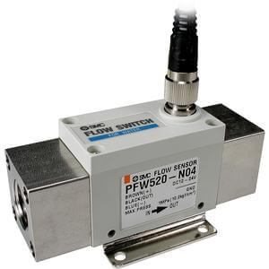
5 to 40 L/min
10 to 100 L/min
27
67
Output specifications
NPN open collector 2 outputs
PNP open collector 2 outputs
Flow rate range
Nil
N
F
Thread type
Rc
NPT
G
Nil
M
With unit switching function
Note1)
Fixed SI unit
Note2)
Unit specifications
Water
Karman vortex
3-digit, 7-segment LED
NPN open collector: Maximum load current: 80 mA; Internal voltage drop: 1 V or less (with load current of 80 mA); Maximum applied voltage: 30 V; 2 outputs
PNP open collector: Maximum load current: 80 mA; Internal voltage drop: 1.5 V or less (with load current of 80 mA); 2 outputs
NPN or PNP open collector (same as switch output)
L/min, gal(US)/min
L, gal(US)
0 to 1 MPa
1.5 MPa
0 to 999999 L
Operating: 0 to 50°C, Stored: –25 to 85°C (with no freezing and condensation)
Lights up when output is ON, OUT1: Green; OUT2: Red
1 sec. or less
Hysteresis mode: Variable (can be set from 0), Window comparator mode
Note 6)
: 3-digit fixed
12 to 24 VDC ±10%
Measured fluid
Flow rate measurement range
Set flow rate range
Rated flow range
Minimum set unit
Accumulated pulse flow rate exchange value (Pulse width: 50 ms)
Operating fluid temperature
Accuracy
Repeatability
Temperature characteristics
Note 1)
Current consumption (No load)
Weight
Note 2)
Port size (Rc, NPT, G)
Detection type
Indicator light
Operating pressure range
Proof pressure
Accumulated flow range
Note 4)
Ambient temperature range
Status LED’s
Response time
Hysteresis
Power supply voltage
Instantaneous flow rate
Accumulated flow
Display units
Note 1) In the case of PF2W711, ±3% of F.S. or less (15°C to 35°C, 25°C reference). Note 2) Without lead wire.
Note 3) For digital flow switch with unit switching function. (Fixed SI unit [L/min or L] will be set for switch type without the unit switching function.)
Note 4) Accumulated flow rate is reset when the power supply turns OFF. Note 5) Switch output and accumulated pulse output can be selected during initial setting.
Note 6) Window comparator mode — Since hysteresis will reach 3 digits, keep P_1 and P_2 or n_1 and n_2 apart by 7 digits or more.
(In case of output OUT2, n_1, 2 to be n_3, 4 and P_1, 2 to be P_3, 4.) Note 7) This product conforms to the CE marking.
PF2W720PF2W704Model PF2W740 PF2W711
460 g
3/8
700 g
1/2, 3/4
1150 g
3/4, 1
520 g
3/8, 1/2
0.35 to 4.5 L/min
0.35 to 4.5 L/min
0.5 to 4 L/min
0.05 L/min
0.05 L/pulse
3.5 to 45 L/min
3.5 to 45 L/min
5 to 40 L/min
0.5 L/min
0.5 L/pulse
7 to 110 L/min
7 to 110 L/min
10 to 100 L/min
1 L/min
1 L/pulse
1.7 to 17.0 L/min
1.7 to 17.0 L/min
2 to 16 L/min
0.1 L/min
0.1 L/pulse
±5% F.S.
±3% F.S.
70 mA or less
±3% F.S.
±2% F.S.
80 mA or less
Switch output
Accumulated pulse output
Output
specifications
PF2W704, PF2W720
PF2W720, PF2W740
PF2W740, PF2W711
PF2W711
Port size
Symbol
03
04
06
10
3/8
1/2
3/4
1
4
쎲
16
쎲
쎲
40
쎲
쎲
100
쎲
쎲
Port
size
Applicable model
Flow rate (L/min)
Enclosure
Operating temperature range
Withstand voltage
Insulation resistance
Noise resistance
IP65
0 to 50°C
1000 VAC for 1 minute between terminals and housing
50 MΩ or more (500 VDC measured via megohmmeter) between terminals and housing
1000 Vp-p, Pulse width 1 µs, Rise time 1 ns
±5% F.S. (0 to 50°C, 25°C reference)
0 to 50°C
Nil
N
Lead wire (Refer to page 322.)
Lead wire with M12 connector (3 m)
Without lead wire
Note1) Under Japan's new
Measurement Act, this is
only for overseas sales (SI
units are to be used inside
Japan).
Note2) Fixed units:
Instantaneous flow rate: L/min
Accumulated flow: L
Specifications
Note 3)
Note 5)
Environment
PF2W7 20 03 27 M
Integrated
Display Type
302
Series PF2W
Digital Flow Switch
For Water